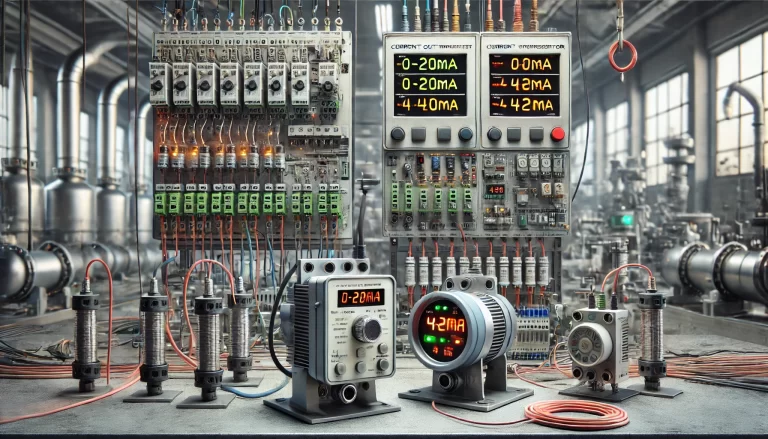
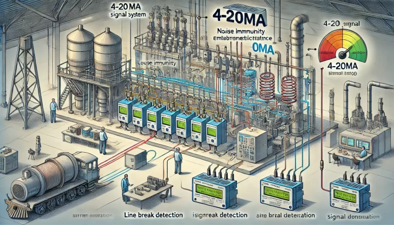
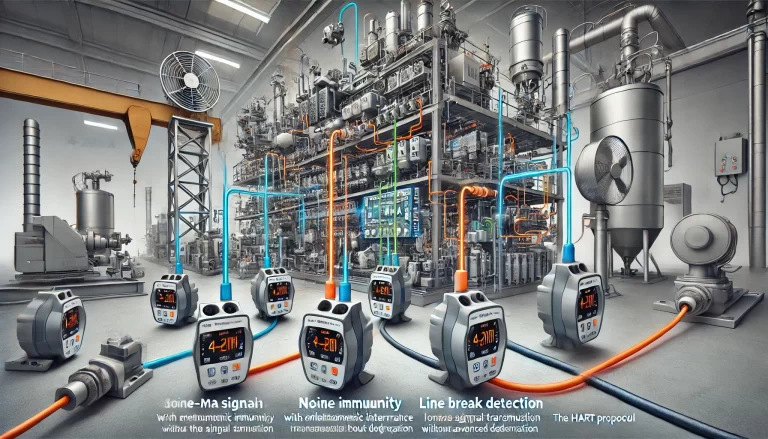
Current output transmitters are essential devices used in industrial automation and control systems for transmitting sensor signals over long distances without being affected by electrical noise. Among the most commonly used standards are the 0–20mA and 4–20mA current output ranges. While both are designed to transmit analog signals, they serve different purposes and have distinct characteristics that influence their application. In this article, we will explore the key differences between these two current output standards, highlighting their strengths and use cases.
1. Range of Operation
The most obvious difference between the two systems lies in their operating range:
- 0–20mA: In this range, the transmitter outputs current starting from 0mA up to a maximum of 20mA. The 0mA signal corresponds to the lowest possible value of the measured parameter, while 20mA represents the highest.
- 4–20mA: In this system, the transmitter starts from 4mA and goes up to 20mA. The 4mA signal corresponds to the lowest possible value, and 20mA represents the highest.

2. Zero-Point Detection
The major distinction between these two ranges is how they handle the zero-point signal:
- 0–20mA: Since 0mA is part of the operational range, it represents a valid signal corresponding to the minimum measured value. However, this introduces a challenge. In the event of a system failure, such as a disconnected wire or transmitter malfunction, the current could also drop to 0mA. This makes it difficult to distinguish between a valid zero-level signal and a failure in the system.
- 4–20mA: The 4mA starting point addresses this problem. With 4mA set as the minimum signal, any reading below that (typically near 0mA) indicates a fault in the system, such as a broken wire or malfunctioning transmitter. This safety feature makes the 4–20mA system more reliable and easier to troubleshoot in industrial applications.
3. Improved Fault Detection with 4–20mA
One of the primary reasons for the widespread adoption of the 4–20mA standard is its built-in ability to detect faults. Since the range never includes 0mA as a valid signal, any current drop to or near 0mA is an indication of a problem. This makes maintenance teams’ jobs easier, as they can quickly identify and rectify issues like:
- Broken or disconnected wiring.
- Transmitter failure.
- Sensor malfunctions.
In contrast, with a 0–20mA system, if the transmitter is sending 0mA, there is no immediate way to differentiate between a genuine low reading and a fault in the system without additional diagnostic equipment.

4. Power Consumption and Efficiency
The 4–20mA system also improves efficiency in terms of power consumption. Because the transmitter always uses a minimum of 4mA, it can operate with more stable power supply characteristics. In a 0–20mA system, where the current might drop to 0mA, certain types of transmitters may lose power, causing them to stop functioning entirely. The continuous current in the 4–20mA system ensures that the transmitter remains powered even at the lowest signal level, ensuring consistent and reliable operation.
5. Noise Resistance and Signal Integrity
Both current transmission standards are generally robust when it comes to resisting electrical noise and interference. Current signals are preferred in industrial environments over voltage signals, as they are less susceptible to degradation over long cable distances and in noisy environments. However, in 0–20mA systems, where the signal can be as low as 0mA, small amounts of noise could be misinterpreted as valid signals, potentially introducing errors.
In a 4–20mA system, the minimum signal of 4mA provides better separation from noise. This margin helps ensure that even in the presence of electrical interference, the signal can still be accurately interpreted by the receiving equipment. Additionally, since current signals are not affected by voltage drops over long distances, they maintain signal integrity over large-scale industrial sites.

6. Historical and Modern Applications
0–20mA: This standard was used more frequently in older systems and applications where fault detection wasn’t as critical. It’s still used in some specific cases where cost is a major concern, and precise fault detection isn’t required.
4–20mA: Today, the 4–20mA system is considered the industry standard in most modern industrial applications. It is preferred for its improved fault detection, stability, and reliability. It is widely used in sectors such as oil and gas, manufacturing, and process control, where accurate data transmission and real-time system monitoring are essential.
7. Compatibility with Existing Equipment
When selecting a current transmitter, it’s also essential to consider compatibility with the receiving equipment. Many modern industrial controllers, data acquisition systems, and programmable logic controllers (PLCs) are designed to accept 4–20mA signals as their standard input. Some older systems may still be configured for 0–20mA signals, but as most industries migrate toward more advanced technologies, the 4–20mA standard is becoming the norm. Therefore, for most new installations or upgrades, the 4–20mA option is typically the better choice.

Conclusion
In summary, the key differences between 0–20mA and 4–20mA current output transmitters revolve around their operational range, fault detection capabilities, and efficiency. The 4–20mA system offers significant advantages, particularly in terms of fault detection, power stability, and noise immunity, making it the preferred choice for most modern industrial and automation applications. While the 0–20mA range still finds some use, particularly in legacy systems, it lacks the built-in safety and reliability features that make 4–20mA the dominant standard in today’s demanding industrial environments.
For those designing or upgrading systems, the 4–20mA standard should be the go-to option, offering enhanced functionality and ensuring long-term compatibility with industry practices.
