1. General requirements
① The appearance of the instrument is in good condition, without paint peeling or loose parts. There are no defects that affect the use and measurement performance, and the dust cover is complete (except for the pressure gauge that does not allow the measured medium to escape from the gauge).
② Instrument zero position inspection: For a pressure gauge with a stop pin, the pointer should be close to the stop pin when there is no pressure, and the pointer of a pressure gauge without a stop pin should be located within the zero position mark.
③ Inspection of insulation resistance of electric contact pressure gauge: Check with a 500V megohmmeter, read after stabilization for 10 seconds, and the insulation resistance is greater than 20MΩ.
④ Inspection of oil-free pressure gauge: Inject warm water (30~40℃) into the meter, and there should be no oil on the water surface after it comes out.
⑤ Selection of calibration points: Determine that there should be no less than 5 pressure calibration points, and select according to the graduation lines marked with numbers. When the upper limit of the pressure measurement of the pressure vacuum gauge is 0.15 (0.06) MPa,
⑥ Two (three) points of the vacuum part are calibrated. When it is greater than 0.3 MPa, the pointer should be able to point to the vacuum direction when evacuating. The electric contact pressure gauge should be checked for set point deviation.
⑦ Calibration working medium: For pressure gauges with a measurement upper limit not greater than 0.25 MPa, the working medium is clean air or other gases with stable performance. For pressure gauges greater than 0.25 MPa, the working medium should be non-corrosive liquids such as turbine oil, and the application air marked with oil prohibition should be used for calibration.
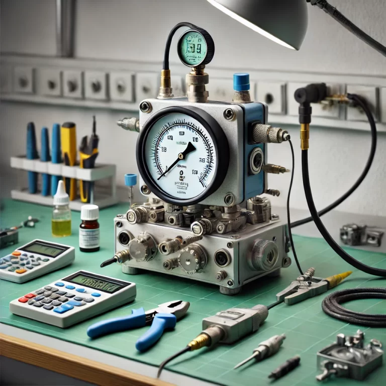
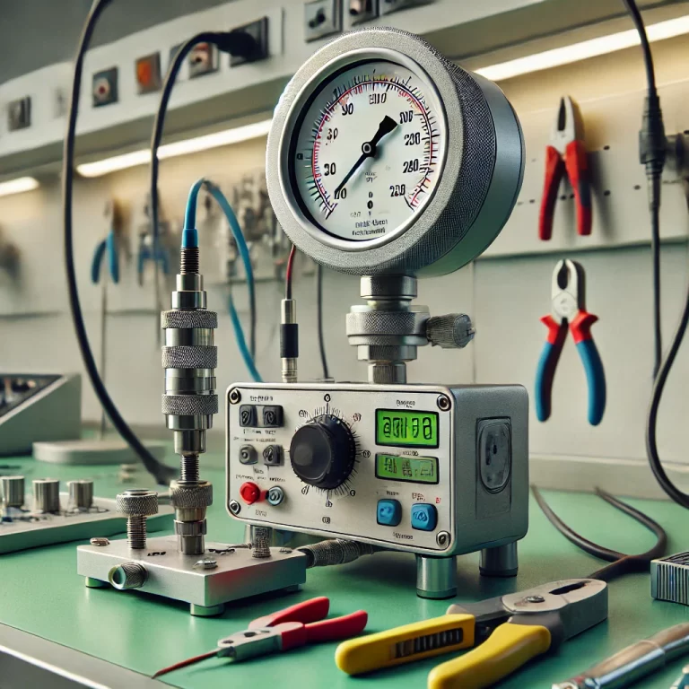
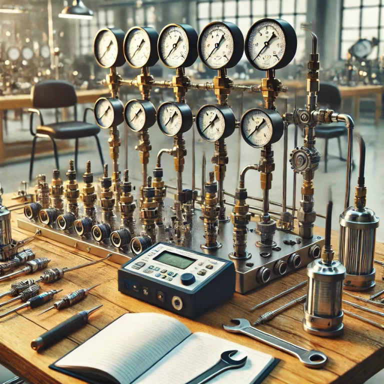
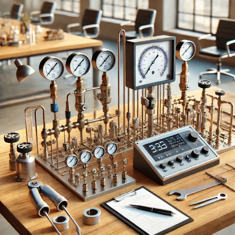
⑧ Installation: Install the gauge to be tested and the standard pressure gauge on the pressure calibration table, and the gauge to be tested should be installed on the left. The pressure points of the two gauges should be basically on the same horizontal plane, otherwise consider liquid column correction.
⑨Seal inspection: Use a pressure pump (vacuum pump, air compressor) to steadily increase the pressure (or evacuate). When the indicated value reaches the upper limit of pressure (or evacuates to 0.08MPa), stop and withstand the pressure for 3 minutes (or as required by the manufacturer), check for leakage, and then drop to zero. The instrument pointer should move smoothly without jumping or getting stuck in the full stroke.
⑩Instrument migration: If the installation position of the instrument is not on the same horizontal plane as the measuring point, make corrections according to the following formula during calibration: P = P1 ±ρ g h (use “+” when the measuring point is higher than the installation position)
P is the standard gauge pressure; P1 is the gauge pressure; ρ is the density of the measured medium;
g is the acceleration of gravity;
h is the vertical height between the installation position of the instrument and the side point position; The following method can be used to roughly estimate on site: the drop of a 10-meter water column is 0. 1Mpa;

2. Instrument calibration
Pressure gauge calibration: According to the specified inspection points, the pressure of the instrument is slowly increased (or decreased) to each pressure inspection point, and the meter is read twice (the meter being inspected). The first time, tap the front of the meter case to read the reading, and the second time, tap the back of the meter case to read the reading. When reading, align the standard meter pointer with the scale, read the calibration meter, read the minimum resolution value (1/5 of the minimum scale value), and record it.
Vacuum gauge calibration: According to the specified inspection points, the pressure of the instrument is slowly vacuumed (or evacuated) to each pressure inspection point
(the maximum value can be set to -0.08Mpa), and the meter is read twice (the meter being inspected). The first time, tap the front of the meter case to read the reading, and the second time, tap the back of the meter case to read the reading and record it.

3. Electric contact pressure gauge calibration
① For electric contact pressure gauge, adjust the contact stopper to the maximum or minimum. Then calibrate according to the pressure gauge and vacuum gauge calibration method.
② Adjust the stopper to the set value (alarm point), check the alarm deviation, and slowly increase (or decrease) the pressure until the signal is connected or disconnected. The value read at this time is the upper (lower) switching value, and the difference between the set value and the value should be less than the allowable error of the instrument.
③ The difference between the values read when the signal is connected or disconnected is the switching difference, which should be less than the absolute value of the allowable error of the instrument.
Pressure vacuum gauge calibration method: calibrate the vacuum part first and then the pressure part. The method is the same as the pressure gauge and vacuum gauge calibration method.

4. Pressure switch
①Select a precision pressure gauge of the corresponding range, install the precision pressure gauge on the left side of the pressure calibration table, and install the calibrated pressure gauge on the right side of the pressure calibration table.
②Push the appropriate pressure transmission medium into the oil cup, close the oil cup valve, slowly rotate the handwheel to pressurize, exhaust the air in the pressure pipe, and check whether the pressure pipe is unobstructed.
③The pressure switch outputs switch quantity information in the form of contact closure and disconnection. For example, when the measured pressure is small, the contact is closed; after the measured pressure increases, the contact is disconnected; it is called a low value (or low limit) contact. If the measured pressure is small, the contact is disconnected; after the measured pressure increases, the contact is closed; high value (or high limit) contact.
④When the pressure rises to the action value specified by the pressure switch, adjust the adjustment knob of the pressure switch to make the contact of the pressure switch move.
⑤The action error of the pressure switch is less than the absolute value of the basic error.
Data rounding: The calculated values and readings in the instrument records must be rounded to 1/5 of the minimum scale that the calibrated instrument can read. For example, if the 1/5 value of the minimum scale is 0.05 (0.02; 0.01) MPa, then it can be rounded to two decimal places according to multiples of 5 (2; 1).
⑥ Calculation of instrument error: instrument indication error ≦ instrument allowable error
Instrument return error ≦ instrument allowable error absolute value, tapping displacement ≦ 1/2 of the instrument allowable error absolute value, signal action alarm deviation ≦ instrument allowable error absolute value
a. Instrument indication error is the difference between the indication before and after tapping the case during calibration and the standard indication value.
b. Instrument return error is the difference between the reading after tapping the case when rising (or falling) to each pressure calibration point during calibration.
c. The instrument tapping displacement is the change in the indication caused by tapping the case before and after rising (or falling) to each pressure calibration point during calibration.
d. The signal action alarm deviation is the difference between the set value and the actual pressure value when the signal is connected and disconnected when rising (or falling) to the set point.
⑦ Record filling: Fill in the contents of the record form according to the instrument requirements, and the data is true and reliable.
⑧ Check the instrument for other items according to the calibration procedures and inspection requirements.
⑨ Instrument adjustment: When the instrument has a linear error, adjust the connecting screws of the pull rod and the fan gear. Move outward to reduce the indication value, and move inward to increase the indication value. When a nonlinear error occurs, adjust the angle between the pull rod and the fan gear. The error is first negative and then positive. Reduce the angle, and then adjust according to the linear error until the error is within the allowable error range.
⑩ After the instrument passes the calibration, affix the certificate and keep a record. If it fails, the reasons must be listed and reported to the team leader and technician.

