1. The orifice flowmeter should be equipped with a section of measuring tube during installation. At least one 10DN and a second 5DN straight pipe section should be maintained to improve measurement accuracy.
2. If valves need to be installed before and after the orifice flowmeter, it is best to choose a gate valve and fully open it during operation; the regulating valve should be in the pipeline after 5DN downstream.
3. The pressure piping should be supported by solid brackets. Two pressure-bearing pipes should be as close as possible and away from sources of heat or vibration. When measuring water vapor flow, they should be bonded together using insulation materials. If necessary (such as when the temperature is below 0°C), heating pipes should be added to prevent freezing. When measuring dirty flow, an isolator or settler should be attached.
4. The pressure pipeline must always maintain a single-phase fluid state. When the fluid to be measured is a gas, the pressure introduction pipe (including the pressure chamber of the differential pressure gauge) is in the gas phase; when the fluid to be measured is a liquid, the pressure introduction pipe is filled with the liquid phase and there must be no bubbles. Therefore, the discharge valve should be installed at the low point of the pressure introduction pipe, or the discharge valve should be installed at the high point of the pressure introduction pipe. Special attention should be paid when installing or repairing the differential pressure transmitter.
5. When measuring liquid flow, if the throttling element is installed on a vertical pipe and the pressure introduction pipe is separated by a certain distance (in the vertical direction), this will affect the zero point of the differential pressure transmitter and should be corrected by “zero point migration”.
6. The straight pipe section used for the orifice flow meter throttling piece should be lubricated. If there is no lubrication, the flow coefficient should be multiplied by the roughness to correct for rarefaction.
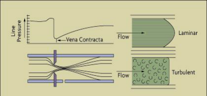
7. In order to ensure that the flow of fluid occurs one day before the throttle, forming rich turbulent velocity dispersion and making the dispersion into an average axially symmetric shape, the straight pipe section must be round.
When the throttling device is installed in horizontal or inclined pipelines, the orientation setting requirements for the sampling port are:
1. When measuring gas flow, the sampling port should be in the upper half of the pipe.
2. When measuring liquid flow, the sampling port should be within the angle range of 0-45° between the lower half of the pipe and the horizontal centerline of the pipe.
3. When measuring steam flow, the sampling port should be within the angle range of 0-45° between the upper half of the pipe and the horizontal centerline of the pipe.