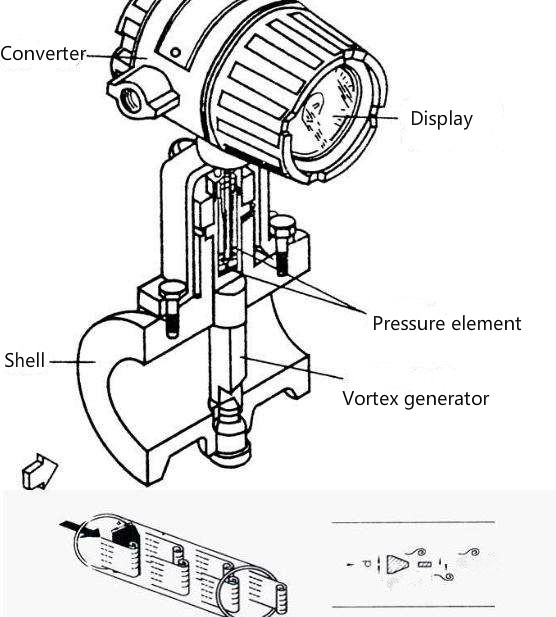
Vortex flowmeter is commonly used in industrial pipeline media fluid flow measurements, such as steam, compressed air and general gas, thermal oil and high-temperature liquids, natural gas, and so on.
As a testing instrument, as with all instruments, in the selection, installation, and use of the process, the need to follow the relevant provisions of the regular inspection, a long time more or less will appear certain problems.
What to look for when choosing a vortex flow meter:
(1) Due to improper selection of the vortex flowmeter, after installation and put into use, the actual flow rate and the range of the instrument are far from the range.
Mainly in the pipe diameter, small flow rate, low flow rate, the actual flow rate in the lower limit of the meter or the lower limit of the following, the meter can not operate normally, the flow measurement error is large;
(2) Selection of the meter, The working condition parameters are provided incorrectly, and the actual working conditions are far from the actual difference, resulting in improper selection of the meter.
Instrumentation installed into operation, can not operate normally, this situation occurs more often in the selection of gas flow flow measurement.
For example, the choice of vortex flow meter flow measurement of compressed air flow, according to the upper limit of the air compressor’s upper working pressure 0.9Mpa (adiabatic) to provide the working pressure, and the actual pressure of the instrument is only 0.3Mpa (adiabatic). If the volume flow rate is calculated in accordance with the pressure of 0.9Mpa and the upper limit volume flow rate, and debug the upper limit volume flow rate corresponding to the 20mA output signal. After the field input, the valve opening is not large, and the output signal has reached full-scale 20mA. This is because the actual working pressure (0.3Mpa) when the volume flow rate than the design of the table (0.9Mpa) when the volume flow rate of 3 times larger due to the design pressure.
When this happens, the only way to readjust the range, that is, according to the working pressure of 0.3Mpa to calculate the working state volume flow, adjust the upper limit of the range.
Possible malfunctions due to improper installation
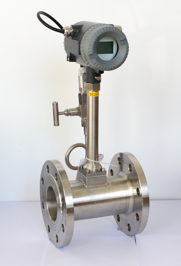
(1) Instrument upstream and downstream straight section length is not enough, the gasket convexs into the pipeline, the sudden contraction of the pipeline, the sudden expansion of the flow stopper, the flow field produces serious disturbances.
(2) The liquid flow measurement containing trace gases or gas flow measurement containing trace liquids of poor installation, resulting in dissimilar flow media in the vortex flowmeter flow measurement pipeline stagnation, causing interference with the flow measurement.
(3) Flow measurement of liquids when the vortex flowmeter installed in the top-down vertical flow or downward sloping flow of the pipeline, or the vortex flowmeter installed in the pipeline outlet without back pressure, resulting in the liquid is not full of pipe.
(4) The vortex flowmeter installation location from the power source (fan, pump) is too close, there is no long enough upstream straight section and effective vibration damping measures.
(5) flow measurement of high-temperature media when the vortex flowmeter horizontal positive installation, the converter is located in the pipeline directly above the pipeline, pipe insulation measures are not in place, resulting in high-temperature pipeline directly on the converter baking, causing damage to electronic components.
(6) Electrical installation errors or supply voltage is not normal, the meter converter can not work properly, or even damaged.
On-site fault analysis and handling measures
No signal output when there is medium flow in the pipeline or instantaneous flow without display
1. First check whether the circuit wiring and power supply voltage are correct;
2. Confirm that there is indeed flow in the pipeline and that it is greater than the lower limit of measurable flow;
3. Check whether the setting of the small flow cut-off value is too large;
4. If the circuit wiring and supply voltage are correct, adjust the sensitivity potentiometer and amplification potentiometer clockwise to the bottom. If the flow rate is still not displayed, the cumulative amount of no change, indicating that there are problems with the circuit board, you need to replace the amplifier board; if there is a signal output, you should check whether the medium flow in the pipeline is beyond the vortex flow sensor measurable flow range; if the medium flow in the measurable range, the sensor’s sensing head sensitivity has been low, you need to re-adjust the sensitivity;
5. Check whether the sensor is good or bad. The sensing head of the two leads from the amplifier board was removed, using a multimeter to measure the sensing head of the resistance between the two leads and the sensing head of the two leads respectively on the shell of the resistance value should be greater than 2MΩ, otherwise, the need to replace the sensing head;
6. If there is no problem with the sensor, check whether the pressure transmitter and platinum RTD are damaged, if there is no problem, it can be judged that the intelligent flow totalizer is damaged.
There is no medium flow in the pipeline and there is a signal output or instantaneous flow rate is displayed
1. First confirm that there is really no medium flow or disturbance in the pipeline, check whether the intensity of pipeline vibration is too large, if the vibration is large, please dampen the vibration in accordance with the following methods: 2D downstream of the flowmeter to add pipeline support points; in order to meet the requirements of the straight pipeline under the premise of the addition of the hose over;
2. Adjust the sensitivity potentiometer counterclockwise until there is no signal output or the instantaneous flow rate back to zero. When adjusting the potentiometer, try to be slower and pause for more than 10 seconds for every 5 degree angle adjustment in order to observe whether the output returns to zero.
Irregular and unstable signal output or unstable instantaneous flow range
1. First check whether the medium flow in the pipeline exceeds the measurable flow range of the sensor;
2. If the medium flow is in the measurable range, check before and after the straight section of the pipe to meet the requirements, and to confirm that the medium in the pipeline is in a stable flow state, with no two-phase flow or pulsating flow phenomenon in the pipeline;
3. Check whether the vibration intensity of the pipeline is too large, if it is too large, please solve the problem according to the method in fault 2;
4. Check whether there is a strong electrical interference signal around the instrument, if so, strengthen the shielding and grounding;
5. Check whether the sensor is tainted, damp, damaged, poor lead contact, if so, please clean or replace the sensor, and tighten the lead;
6. Check whether the sensor installation is concentric or the gasket is convex into the tube, if any installation, adjust the gasket’s inner diameter;
7. Check the sensitivity of the sensor, and adjust the sensitivity; 8. Check whether the process is stable, adjust the installation position;
9. Check whether there is any entanglement on the generator body;
10. Check whether there are air pockets in the pipeline, if so reduce the flow rate and increase the pressure in the pipe.
High measurement error
1. Firstly, check whether the supply voltage of the meter is too large;
2. Check if the meter’s analog conversion circuit zero drift or range adjustment is not correct, if so, please correct the zero and range scale.
3. Check whether there are problems such as 1, 2, and 5 in fault 3;
4. Check whether the meter exceeds the calibration cycle;
5. Check whether there is leakage in the pipeline.
Measuring tube leakage
1. Check whether the pressure in the pipe is too high;
2. check whether the nominal pressure selection is correct, if not, please choose a higher nominal pressure sensor;
3. Check whether the seals are damaged;
4. Check whether the sensor is corroded, if so, should take anti-corrosion and protective measures.
Abnormal whistling sound from the sensor
1. Check whether the flow rate is too high, causing strong trembling, if so, please adjust the flow rate or replace the meter with a large throughput;
2. Check whether the phenomenon of air cavity occurs, if so please adjust the flow rate and increase the pressure of liquid flow;
3. Check whether the generator is loose.
Meter display temperature error
1. Check the wiring for errors and broken wires;
2. Measure its resistance at approximately 1080 ohms (at room temperature);
3. Consult the manufacturer according to what is measured.
Meter shows pressure error
1. Check if the wiring is wrong and disconnected;
2. Measure its resistance value of about 5000 ohms at room temperature;
3. Consult the manufacturer according to what is measured.
