What is an Electric Actuator?
Simply put, an electric actuator is a device that constructs the movement of a load or an action that requires a force like clamping, which requires the implementation of an electric motor to create the necessary force needed.
What are the Component Parts of an Electric Actuator?
Front / Rear Clevis
A Clevis is a U-shaped piece of metal with is punctured with holes in each end to be run through by a fastening device such as a pin or a bolt. The attachments at the front end and back end of a clevis make room for the possibility of it being mounted on the application that is desired.
Outer Tube
This is also identified as the cover tube which is an extruded aluminum tube with the function of protecting the outside of the linear actuator while it also performs the responsibility of housing all of the actuator’s inner mechanisms.
Inner Tube
This can also be identified as the extension tube, the drive tube, the translating tube, or the piston; this is normally constructed out of aluminum or stainless steel. While it is in a retracted state, the inner tube is the location the spindle is naturally positioned. This tube is attached to the threaded part of the drive nut while it extends and also retracts as the drive nut travels along the revolving spindle.
Spindle
The spindle—which is naturally known as the lead screw, rotating screw, or lifting screw—is a rod that is long and straight and turns in a machine or tool. The nature of the spindle is to rotate, extend or retract the nut/inner tube; this, in turn, creates a linear motion and can be considered to be the linear actuator segment.
Safety Stop
This which is found at the rear of the spindle has the function of preventing the inner tube from overextending beyond its designed reach.
Wiper
A wiper by its design is a sealing component that is attached to the rear of the outer tube with the responsibility of protecting the actuator’s spindle area from being contaminated with dust and liquids.
It also acts as a proper seal between the inner and outer tubes, which in turn influences the linear actuator’s IP rating.
Drive Nut
This can be an acme or ball screws that are attached to the inner tube and move along the spindle. This is the component that allows the extension or retraction of the inner tube. It can be constructed off metal or plastic and most times it is keyed to prevent inner tube rotation.
Limit Switches
This controls the fully extended and retracted inner tube position by cutting the supply of electric currents to the motor within. These switches are tasked with the role of not letting the actuator overextend or over retract. In addition to this, limit switches also double as signal-sending devices.
Gear
This is constructed with steel or plastic and it is designed to mate with other gears to alter the relationship between the speed of a drive mechanism (an example of this is the engine of a vehicle) and the speed of the driven parts (like the wheels of the vehicle). The gear which is connected to a power source such as a motor is known as the DRIVE GEAR.
Motor Housing
This is the location that stores all the internal parts of the gear motor without exposing anything to damage by external forces.
DC Motor
The DC (Direct Current) motor is the location where all the electric linear actuator’s electrical power is generated.
Stator
This portion of the motor is designed to be stationary and it consists of the motor housing, two permanent magnets, and motor caps. This portion—the stator—is responsible for generating the stationary magnetic field that surrounds the rotor.
Rotor
The rotor which also goes by the name armature is the inner part of the motor system that rotates; it is mainly constructed using silicon laminate, motor shaft, commutator, and copper windings.
Commutator
By design, the commutator is a pair of plates that are attached to the motor shaft; these plates are tasked with providing two connections for the coil of the electromagnet. The commutator is designed to be a reversal mechanism for the motor’s polarity which essentially keeps the motor rotating without its torque dissipating.
Carbon Brushes
The carbon brushes employ the use of sliding friction to transmit electrical current from the stator to the rotor in the motor.
Motor Shaft
The motor shaft on the DC motor ensures the connection between the gear motor and the base of the stator.
Output/Feedback Sensors
These are used to communicate the actuator’s current stroke position, the feedback that it gives is directly sent to the control box MCU (micro control unit). When an application involves high-level functions, the linear actuators with position feedback are naturally employed in situations such as synchronization and memory positioning.
Output sensor options include:
Hall Effect Sensor
The Hall Effect sensor’s output signal is a result of the magnetic field density which surrounds the device. If the sensor’s magnetic flux density exceeds a certain pre-set threshold—which is set in the MCU—the sensor immediately identifies this and generates an output voltage called the Hall Voltage.
One of the major importance of a linear actuator with position feedback is its reliability and accuracy which is exactly what the Hall Sensor provides
Potentiometer (POT) Sensor
A POT sensor has two end connectors and a wiper or slider that modifies the output of an electrical signal. The resistance between the wiper/slider and the two end connectors changes when the linear actuator lead screw (spindle) rotates. There will be a place in the actuator’s stroke for each resistance value.
Reed Sensor
Reed sensors function as magnetic positioning sensors. It functions as an electrical switch by applying a magnetic field. Two contacts on ferrous metal reeds that are contained in a sealed glass envelope make up the device. The contacts may normally be open, but they close in the presence of a magnetic field, closing the circuit and cutting off power to the actuator.
We hope that this has strengthened your knowledge of electric linear actuators. The options for an actuator’s safety features will be covered next.
How do Electric Actuators Work?
As the spindle, or rotor, turns, an electric motor will provide rotary motion. The driving shaft, which revolves in a ball screw nut, connects the motor spindle directly to a helical screw.
The ball screw nut is moved forward or backward along the helical screw as the spindle revolves.
The linear actuator is moved out of or into as the motor turns clockwise or counterclockwise by a hollow piston rod that is fastened to the ball screw nut.
Adjusting the rotation speed and, as a result, the linear speed of the actuator is possible thanks to the electric drive, which controls the motor. A feedback system gives positioning information, and the linear actuator may be programmed to move to a certain spot, stop, and then continue moving, or return to its rest state.
The power of the motor determines the torque that can be generated and, consequently, the force that can be applied through the actuator.
The Benefits of using Electric Actuators
Efficiency and Energy Savings
Electric actuators offer incredibly precise positioning and control. Additionally, this kind of actuator has a low running cost and aids in the adaptation of machines to flexible processes. This indicates that an electric system is cost-effective and efficient in terms of energy use.
In situations where numerous points of placement are necessary, electric actuation is the most effective choice. This is because to carry out the same kinds of motion, pneumatic cylinders require the coupling of several accessories. Long-term, this results in greater costs and decreased accuracy and efficiency.
Electric actuators are superior to pneumatic or hydraulic ones in another way: they can start and stop practically instantly when instructed to do so. There are no lags or delays.
To maintain pressure on pneumatic cylinders, your compressor must work continuously. On the other hand, electric actuators only need to operate when work has to be done. This translates into lower power expenditures for your company.
Here are a few other significant benefits of electric actuators.
- very precise placement and control
- being able to halt at any time during a stroke
- Simple acceleration and deceleration controls
- no outside sensors
- a low cost of operation
- assist in converting equipment to flexible processes
- heightened efficiency at high speeds
- very little upkeep
- minimal chance of contamination
The different types of Electric Actuators
Electric actuators are of 2 basic types the linear and the rotary
To transition from open to closed, rotary electric actuators use a butterfly, ball, and plug valves. With the aid of rotary electric actuators, the components spin as a result of the motor’s electromagnetic force, enabling several pauses throughout each stroke.
The rotating element might be either a table or a circular shaft. The torque and range of motion of the electric rotary actuator should be taken into account.
The power that rotates is referred to as the actuator torque, and the whole range of motion can be either nominal, quarter-turn, or multiturn. In contrast, pinch, globe, diaphragm, gate, or angle valves are used by linear electric actuators to open and close.
When precise tolerances are needed, they are frequently employed. These electric actuators generate linear motion using motor-driven ball screws or acme screw assemblies.
The load is attached to the end of a screw that is driven by a belt or gear in linear electric actuators. When choosing linear electric actuators, it’s important to take into account the length of the valve stem stroke, the actuating force, and the number of rotations.
Through the use of a motor-driven ball screw or screw assembly, linear electric actuators provide linear motion. The load of the linear actuator is unsupported and is fastened to the end of a screw or rod. The screw may be direct, via a belt, or through a gear.
When choosing linear actuators, it’s important to take their stroke, maximum rated load or force, maximum rated speed, continuous power, and system backlash into account. The distance between the fully extended and fully retracted rod positions is known as the stroke. The maximum static load is not the maximum rated load or force.
The highest possible force or load is not the highest possible rated load. The maximum rated speed of the actuator, which is normally established under low or no load, determines its maximum linear speed. The power that is always available is regarded as sustainable; short-term peak power ratings are excluded. Backlash is a positional inaccuracy brought on by a change in direction.
In addition to stepper and DC (direct current) motors, there are also DC servo, DC brushless, and DC brushless servo motors. Stepper motors, DC motors, and AC motors all have input power options.
Drive screw type and screw lead are the two drive screw requirements for linear actuators.
Limit switches, motor encoder feedback, self-locking, and linear position feedback are some of the characteristics. There are acme screws and ball screws available as screw alternatives.
The output shaft is rotated incrementally using rotary electric actuators. A rotary actuator’s most basic configuration comprises a motor and a speed reducer. It is possible to construct these AC and DC motors with the precise voltage, frequency, power, and performance required.
The desired speed, torque, and acceleration are matched with the appropriate speed reducer. Considerations like life, duty cycle, limit load, and precision also affect the choice of the speed reducer. Antifriction bearings are used as standard in these speed reducers to support hardened, precise spur gears. Compound gear reduction is possible in planetary shapes, compact, numerous load route arrangements, and more.
The angular rotation, torque, speed, control signals, feedback signals, and ambient temperature are among the requirements for rotary actuators.
Different auxiliary parts, such as brakes, clutches, anti-backlash gears, and/or unique seals, can be included in rotary actuators. It is also possible to use redundant methods that combine the velocity or torque of two or more motors. In many applications nowadays, linear actuator motion is transformed into rotational motion. Some fittings in the bed can be spared by directly supplying the rotating motion.
Due to this, a rotational actuator rather than a linear actuator may be integrated into the bed much more elegantly. The actuator is no longer perceived as a product hanging beneath the bed but rather as a component of the bed, creating a purer design.
Rotary electric actuators are used with modulating valves, ranging from quarter turn to multiturn valves. Electrically operated multiturn actuators are among the most well-known and dependable actuator configurations. An electric motor operating in one or three phases turns a series of spur and/or level gears to drive a stem nut. The stem nut makes contact with the valve stem to open or close the valve, often utilizing an acme threaded shaft. The ability to quickly operate very large valves is a feature of electric multiturn actuators.
How to Choose the Best Electric Actuator for your needs?
The actuator is required for applications that need force. Pressure on a piston’s surface area in a pneumatic linear actuator generates force. Electric actuators generate force using the motor’s torque capability. The weight that has to be moved, any surface frictional forces, and the load’s angle of elevation or declination are important considerations.
The load, which must move a certain distance, determines the pneumatic actuator’s stroke. The same is true for an electric actuator, with a few small exceptions. The maximum stroke less than four times the helical screw pitch is the “usable” stroke, which avoids over-run.
An electric actuator can be employed in a variety of locations, therefore the necessary stroke must account for the entire movement. Due to the availability of various screw pitches based on the bore, component combinations can satisfy different application requirements.
It is also helpful to think about situations in which an electric actuator might be better than a pneumatic one. Electricity is the sole option when a compressed air source is not available (if hydraulic solutions also are not available).
The need for many locations in an application is one of the main benefits of electric linear actuators. Additional benefits include more axial force, greater precision, less noise, flexibility in control characteristics, increased load rigidity, and overall lower operating costs.
The Application of Electric Actuator
There are many industrial uses for electric actuators.
Dispensing and a variety of jointing techniques, such as welding, riveting, and gluing, are accessible for autonomous transport vehicles.
PET bottle manufacturing equipment, filling and labeling equipment, and robotic applications such as milking robots are all used in the food and beverage business.
They have frequently been utilized in the material handling and packaging sectors for tasks like servo presses and clamping.
Their application in robotics, electronics, electronic assembly, machine tools, and many other industrial domains is made possible by their advantages in precision, adaptability, and cheap operating costs.
Precautions
- To keep a typically constant working temperature when working in hot weather or surroundings, it’s crucial to make sure the ventilation system is in good operating order. It must be done every two hours when working in a cramped space without ventilation or other required circumstances. Every hour, the machine must be halted for five to ten minutes to ensure proper operation;
- Caution should be used while operating in areas with high air humidity and a humid atmosphere to prevent damage to the operator from leaks caused by humidity. To prevent such occurrences, it is crucial to pay closer attention to the wear status of electrical circuits and to wear the necessary protective gear;
- Maintaining temperature stability is essential for the push rod to function properly. The viscosity of the lubricating oil working on the machine will vary at an excessive temperature, accelerating the loss of the contact components. Add an appropriate coagulant.
Fault Analysis
Vi signifies a defect induced by a leak or clogged valve in an actuator, for example. Fault vi refers to parameter fluctuations that have a unique physical significance. Root cause analysis (RCA), as used in this study, is the process of identifying these reasons for an actuator problem. To perform root cause analysis, we assume that the actuator subsystem’s local level inputs (u) and outputs (a) will be fed into the FDD approach.
To a significant degree, it is impractical to measure ua in genuine industrial conditions, hence ua is assumed to be inaccessible in this work. However, online diagnosis of actuator components is frequently accomplished via a remote supervisory diagnostic system. Additionally, while performing an FDD function at a local subsystem, information from a global level should be provided to monitor the plant globally.
The difference between Traditional Equipment
When choosing an electric linear motion system, a machine designer takes into account several different elements. Let’s examine how each of these two technologies—traditional and integrated—performs.
- When developing a machine, integration ease must be taken into account.
Traditional actuators require mounting a motor to the actuator, which adds to the integration time. Since the motor manufacturer frequently also produces the servo drive in this scenario, integrating the motor, drive, and controller is typically simple.
The time it takes to enter motor characteristics into the servo drive and then tune the system may be longer with integrated actuators since they do not require motor installation.
- Size takes into account both the envelope and the weight.
External motors for conventional actuators can be positioned parallel or in line with the actuator (also called reverse-parallel). While inline motor mounting increases the configuration’s length, parallel mounting increases its breadth.
The most compact form is offered by integrated actuators.
- Ingress protection is crucial in outdoor and wash-down applications.
Fasteners and joints function as entry routes for moisture and other impurities that might corrode an actuator.
Traditional actuators have several ports of entry because they need extra parts to fit the actuator to the motor.
There are a lot fewer possible entry locations with an integrated actuator.
This crucial entry point is removed since there is no need to attach a motor.
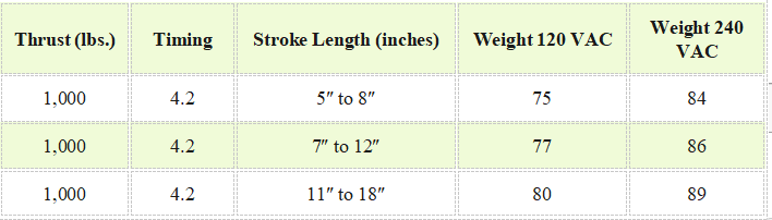
Technical Specifications
OUTPUT THRUST, STROKE TIME, STROKE LENGTH, AND WEIGHT (ALL MODELS)
Summary
When choosing a linear motion system, there are numerous things to take into account. Many various methods will be used. A normal electric linear actuator could be required in some situations; however, an integrated linear actuator might be preferable. Get in contact with us if you have any inquiries or require engineering advice from specialists in linear motion.