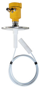
We must first understand what is a guided wave radar level meter? What are the advantages? A guided wave radar level meter is a measuring instrument based on the principle of time-domain reflection. The electromagnetic pulse of the radar level meter travels at the speed of light along a steel cable or probe. When encountering the surface of the measured medium, part of the radar level meter’s pulse is reflected to form an echo and returned to the pulse transmitter along the same path. The distance between the transmitter and the surface of the measured medium is proportional to the propagation time of the pulse between them, and thus the level height is calculated.
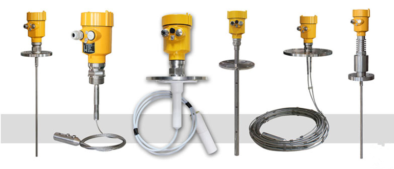
The guided wave radar level meter can measure liquids, particles, and slurries and is unaffected by medium changes, temperature changes, inert gases, vapors, dust, foam, etc. It is suitable for acid and alkali storage tanks, slurry storage tanks, solid particles, small storage tanks, and other complex occasions.
Such a high-quality measuring instrument also needs some tips on installation.
After the first point determines the flow direction of the material to be measured, the mounting point should be selected at a low level in the pipeline. If the error is caused by the indicator not being at the zero position due to the empty level of liquid in the pipe, the mounting point should be selected anytime the pile is filled with liquid.
The second point horizontal direction of the signal electrode, in order to make the electrode axis parallel to the horizontal line during horizontal installation, the bottom electrode will be covered with sediment and the electrode surface will be rubbed by the air bubbles sometimes present in the Measuring medium, fluctuating output signal.
The third point is to try to avoid vibration sources and magnetic sources because the induced voltage of the guided wave radar level meter is very small and low, so the external guided wave radar is vulnerable to noise. So the installation process of grounding connection is more reliable.
The last point’s straight-line length should be kept in front of 5D and behind 3D (D is the nominal diameter of the sensor).In order to obtain the measurement accuracy of the instrument, the level spread length on the upstream side of the sensor should not be less than 5D and the level spread length on the downstream side should not be less than 3D.
If there are two or more angle heads or other baffles on the upstream side, the length of the front straight line should be more than 10d