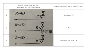
A turbine flowmeter is more sensitive to the influence of the velocity distribution of the inlet fluid. The inlet flow state depends on the piping structure at the inlet of the flow meter. In principle, it is required to have a straight pipe section long enough to eliminate the symmetrical and stable cross-section of the flow velocity of the fluid at the inlet. Figure 1-17 shows the influence of the piping structure at the inlet of the flowmeter on the meter coefficient.
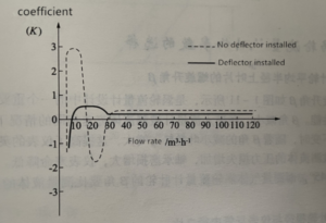
However, in practical applications, due to the limitation of on-site installation conditions, it is impossible to fully satisfy that there is a long enough straight pipe section in front of the flowmeter, and a rectifier can be installed to eliminate the influence of vortex flow. Figure 1-18 is a DN65 turbine flowmeter. The fluid rotation caused by the bending of the pipe affects the meter coefficient and the situation after the rectifier is installed. In addition, the angle between the fluid and the turbine blades is changed due to the gasket protruding to the inside of the pipe when the flow meter is installed, so that the instrument coefficient changes by 2% or more.


