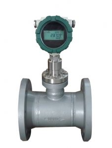
Target flow meters measure flow by measuring the amount of force exerted by the flowing fluid on a target suspended in the flow stream. The force exerted on the target by the flow is proportional to the pressure drop across the target.
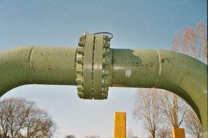
When installing it on the pipe, if there is an existing flange. Then the supplier’s provides should be matched with a flange.
The flange has ASME standards, European Dimensions, and other countries.
A flange is a protruded ridge, lip, or rim, either external or internal, that serves to increase strength (as the flange of an iron beam such as an I-beam or a T-beam); for easy attachment/transfer of contact force with another object (as the flange on the end of a pipe, steam cylinder, etc., or on the lens mount of a camera); or for stabilizing and guiding the movements of a machine or its parts (as the inside flange of a rail car or tram wheel, which keep the wheels from running off the rails). The term “flange” is also used as a kind of tool used to form flanges.
Pls refer to https://en.wikipedia.org/wiki/Flange
ASME standards (U.S.)
Pipe flanges that are made to standards called out by ASME B16.5 or ASME B16.47, and MSS SP-44. They are typically made from forged materials and have machined surfaces. ASME B16.5 refers to nominal pipe sizes (NPS) from ½” to 24″. B16.47 covers NPSs from 26″ to 60″. Each specification further delineates flanges into pressure classes: 150, 300, 400, 600, 900, 1500 and 2500 for B16.5, and B16.47 delineates its flanges into pressure classes 75, 150, 300, 400, 600, 900. However these classes do not correspond to maximum pressures in psi. Instead, the maximum pressure depends on the material of the flange and the temperature. For example, the maximum pressure for a Class 150 flange is 285 psi, and for a Class 300 Flange it is 740 psi (both are for ASTM A105 Carbon Steel and temperatures below 100F).
The gasket type and bolt type are generally specified by the standard(s); however, sometimes the standards refer to the ASME Boiler and Pressure Vessel Code (B&PVC) for details (see ASME Code Section VIII Division 1 – Appendix 2). These flanges are recognized by ASME Pipe Codes such as ASME B31.1 Power Piping, and ASME B31.3 Process Piping.
Materials for flanges are usually under ASME designation: SA-105 (Specification for Carbon Steel Forgings for Piping Applications), SA-266 (Specification for Carbon Steel Forgings for Pressure Vessel Components), or SA-182 (Specification for Forged or Rolled Alloy-Steel Pipe Flanges, Forged Fittings, and Valves and Parts for High-Temperature Service). In addition, there are many “industry standard” flanges that in some circumstance may be used on ASME work.
The product range includes SORF, SOFF, BLRF, BLFF, WNRF (XS, XXS, STD & Schedule 20, 40, 80), WNFF (XS, XXS, STD & Schedule 20, 40, 80), SWRF (XS & STD), SWFF (XS & STD), Threaded RF, Threaded FF & LJ, with sizes from 1/2″ to 16″. The bolting material used for flange connection is stud bolts mated with two nut (washer when required). In Petrochemical industries, ASTM A193 B7 STUD & ASTM A193 B16 Stud Bolts are used as these have high tensile strength.
European dimensions (EN / DIN)
Most countries in Europe mainly install flanges according to standard DIN EN 1092-1 (forged Stainless or Steel Flanges). Similar to the ASME flange standard, the EN 1092-1 standard has the basic flange forms, such as weld neck flange, blind flange, lapped flange, threaded Flange (Thread ISO7-1 instead of NPT), weld on collar, pressed collars, and adapter flange such as flange coupling GD press fittings. The different forms of flanges within the EN 1092-1 (European Norm Euronorm) is indicated within the flange name through the type.
| Design | According to EN type | According to DIN |
|---|---|---|
| Weld-neck flange | Type 11 | DIN 2627 – DIN 2638 |
| Blind flange | Type 05 | DIN 2527 |
| Threaded flange | Type 12 | DIN 2558, DIN 2565 – DIN 2569 |
| Flat flange | Type 01 | DIN 2573, DIN 2576 |
| Lapped flange | Type 02 & Type 04 | DIN 2641, DIN 2642, DIN 2655, DIN 2656 |
Similar to ASME flanges, EN1092-1 steel and stainless flanges, have several different versions of raised or none raised faces. According to the European form the seals are indicated by different form:
| Form: types of contact faces | DIN EN 1092-1 |
|---|---|
| Without raised face | Form A |
| Raised face (Rz = 160 mechanical turned) | Form B1 |
| Raised race ( Rz = 40 mechanical turned) | Form B1 |
| Raised face (Rz = 16 mechanical turned) | Form B2 |
| Tongue according to DIN2512 | Form C |
| Groove according to DIN 2512 | Form D |
| Male according to DIN 2513 | Form E |
| Female according to DIN 2513 | Form F |
| Female according to DIN 2514 | Form G |
| Male according to DIN 2514 | Form H |
Other countries
Flanges in the rest of the world are manufactured according to the ISO standards for materials, pressure ratings, etc. to which local standards including DIN, BS, and others, have been aligned.
Compact flanges
As the Compact flange size increase it becomes relatively increasingly heavy and complex resulting in high procurement, installation and maintenance costs. Large flange diameters in particular are difficult to work with, and inevitably require more space and have a more challenging handling and installation procedure, particularly on remote installations such as oil rigs.
The design of the flange face includes two independent seals. The first seal is created by application of seal seating stress at the flange heel, but it is not straight forward to ensure the function of this seal.
Theoretically, the heel contact will be maintained for pressure values up to 1,8 times the flange rating at room temperature.
Theoretically, the flange also remains in contact along its outer circumference at the flange faces for all allowable load levels that it is designed for.
The main seal is the IX seal ring. The seal ring force is provided by the elastic stored energy in the stressed seal ring. Any heel leakage will give internal pressure acting on the seal ring inside intensifying the sealing action. This however requires the IX ring to be retained in the theoretical location in the ring groove which is difficult to ensure and verify during installation.
The design aims at preventing exposure to oxygen and other corrosive agents. Thus, this prevents corrosion of the flange faces, the stressed length of the bolts and the seal ring. This however depends on the outer dust rim to remain in satisfactory contact and that the inside fluid is not corrosive in case of leaking into the bolt circle void.
Applications of compact flanges
The initial cost of the theoretical higher performance compact flange is inevitably higher than a regular flange due to the closer tolerances and significantly more sophisticated design and installation requirements. By way of example, compact flanges are often used across the following applications: subsea oil and gas or riser, cold work and cryogenics, gas injection, high temperature, and nuclear applications.