The following info is from Krohne Webinar, Zero Instrument prepare.
- Necessity of Grounding
- Grounding: Protective Ground (PE) & Functional Ground (FE)
- Methods of conventional Functional Ground (FE)
- Problems with conventional Functional Ground (FE)
- Improvements in conventional Functional Ground (FE)
- Summary
Necessity of Grounding
Electromagnetic flow measurement (Faraday’s Law)

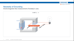


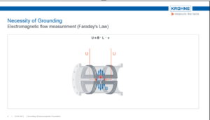

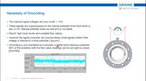
●The induced signal voltages are very small: < 1mV.
●These signals are superimposed on the natural potential of the fluid which is
also in mV. Natural potential varies as well and is not stable.
●Result: high noise levels and unstable flow values.
●However, the signal converter can process these small signals better if this
voltage is referred to as a fixed potential (“ground”).
●Grounding is very important as it provides a stable fixed reference potential.
80% of the problems with the flow value readings can be set right by proper
grounding.
Protective ground (PE) & Functional ground (FE)
Protective Ground (PE)
- Like all electrical equipment, electromagnetic flowmeters must be grounded according to the applicable local safety regulations.
- Converters always have a protective ground terminal for safety.

Functional Ground (FE)
- Essential for accurate and reliable flow readings.
- Processing the small-signal voltage with high resolution is possible only if the difference between the natural potential and reference potential is as small as possible.
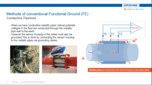
Methods of conventional Functional Ground (FE)
Conductive Pipelines
- When we have conductive metallic pipes natural potential voltages in the fluid are conducted through the metallic pipe wall to the earth.
- However, the sensor housing of the meter must also be grounded. This is done by connecting the sensor housing to the metallic pipes via grounding cables.

Methods of conventional Functional Ground (FE)
Grounding Rings
- Nonconductive pipes like plastic, concrete, internally lined pipes require grounding rings for grounding.
- Grounding rings come in contact with the medium and are connected to the earth via grounding cable9.
- Mounted between the pipe flanges and the flowmeter flanges.
- Grounding rings are available in a variety of materials.

Methods of conventional Functional Ground (FE)
Grounding Electrode
- The grounding electrode is directly connected to the sensor housing and it equalizes the potential voltage difference between the process fluid and the earth.
- Costs less than the grounding rings specially for exotic metals like Tantalum, Platinum etcetera.
- However, in the case of potential voltage difference even as low as 0.2V between the process fluid and the earth, the equalizing current produced damages the grounding electrode electrolytically.
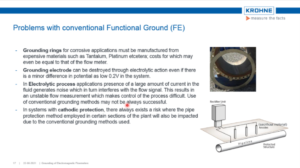
Problems with conventional Functional Ground (FE)
Grounding rings for corrosive applications must be manufactured from
expensive materials such as Tantalum, Platinum etcetera; costs for which may
even be equal to that of the flow meter.
Grounding electrode can be destroyed through electrolytic action even if there
is a minor difference in potential as low 0.2V in the system.
In Electrolytic process applications presence of a large amount of current in the
fluid generates noise which in tum interferes with the flow signal. This results in
an unstable flow measurement which makes the control of the process difficult. The use of conventional grounding methods may not be always successful.
In systems with cathodic protection, there always exists a risk where the pipe
protection method employed in certain sections of the plant will also be impacted
due to the conventional grounding methods used.

Improvements in conventional Functional Ground (FE)
Reference Electrode
- The reference electrode is not connected to the flow sensor housing but is directly connected to the electronics.
- Since there is high input impedance at the op-amp in the signal converter no measurable current can run through the reference electrode.
- Independent of any external connections provided for grounding.
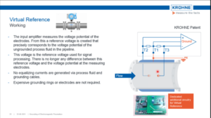
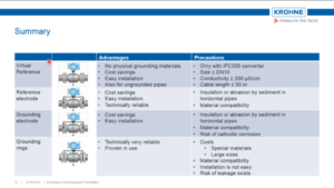
Virtual Reference
Working
The input amplifier measures the voltage potential of the
electrodes. From this, a reference voltage is created that
precisely corresponds to the voltage potential of the
ungrounded process fluid in the pipeline.
This voltage is the reference voltage used for signal
processing. There is no longer any difference between this
reference voltage and the voltage potential at the measuring
electrodes.
No equalizing currents are generated via process fluid and
grounding cables.
Expensive grounding rings or electrodes are not required.
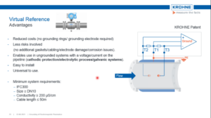
Virtual Reference
Advantages
- Reduced costs (no grounding rings/ grounding electrode required)
- Less risks involved (no additional gaskets/cabling/electrode damage/corrosion issues).
- Enables use in ungrounded systems with a voltage/current on the pipeline (cathodic protection/electrolytic process/galvanic systems).
- Easy to install
- Universal to use.
- Minimum system requirements:
- IFC300
- Size 2 DN10
- Conductivity≥200 μS/cm
- Cable length≤50m