Installation of meters
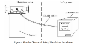
The mass flow meter mostly is divided into two parts: a sensor (primary meter)
and a transmitter (secondary meter), a shielded cable connects two parts. The transmitter(secondary meter) of the essential safety flow meter must mount in the safety area according to prescriptive conditions (see section 3.2). A sensor and a transmitter of the essential safety flow meter installation show in Figure 4.
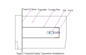
The transmitter (secondary meter) of the essential safety flow meter normally
fixes at a cabinet. Drill a square hatch 152mm X 152mm on the panel of the cabinet; install the transmitter with attached securing plates, nuts, and screws referring to Figure 5.
The transmitter (secondary meter) of composite type mounts on the sensor
(primary meter) with attached screws. A shielded cable connects two parts.
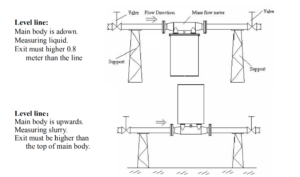
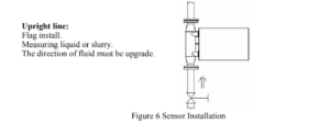
Installation of the sensor shows in Figure 6, illuminate hereinafter now:
(1) The mass flow meter normally installs in a level line, the main body
perpendicularly downwards. PLS pay attention to the direction label on the flow meter, which should be the same as the direction of the fluid in the line. If can not confirm direction, PLS see
Figure 6 and 10, while the cable socket on the back of the mass flow meter, the flow direction is from left to right;
(2) Securing supports should be built-in upper and lower reaches of a line
besides the flow meter;
(3) Ensure concentric with two flanges of flow meter and line while
installation. When screwing, screws should be forced uniformity symmetrically, do
not impose contraposition, forbidden wring or bend the primary meter;
(4) Definite back pressure should keep in the lower reaches of a line behind
flow meter. Do not let line direct open, prevent incorrectly measure while a half tube of liquid;
(5) The sensor (primary meter) must leave up ground, and do not touch anything;
(6) The tube of the upper reaches of the line must equal or large than the meter’s
inner diameter, forbidden to less than;
(7) The body of the sensor should be covered with heat preserved material, for
measuring the liquid that easily gasifies. Or, the sensor may be damaged with frost or dew;
(8) For the type of DN1, DN3, DN6, and DN10, the sensor should install on
ground, use the soft tube to connect to the lines;
(9) The serial number of the sensor and transmitter should same if the serial
number not match, the error may be bigger than normal;
5.2 Conditions required for installation
To guarantee the accuracy, conditions required when installation should be met,
because the mass flow meter is a high precision instrument:
(1) The sensor (primary meter) and the transmitter (secondary meter) do not
install in a strong magnetic interferential area. Or, measuring signals would be disturbed, and debase the accuracy;
(2) There is must not any other vibrator on line installed the sensor (primary
meter);
(3) If install outside of the door, PLS pay attention to circumstance temperature not to exceed the range of the meter, and should consider building a weatherproof shield to avoid blowing and drenching, for increasing lifetime of the flow meter.
(4) The transmitter (secondary meter) of essential safety should mount in safety
area or appropriate control room.
(5) A shielded cable with ten core lines connects the sensor (primary meter) and the
transmitter (secondary meter) of essential safety.
The output cable of the transmitter (secondary meter) of the composite is a shield
cable with ten core lines.
Five meters long of the cable is a normal option in the package by our company.
Customs can deal with special orders for a longer cable, but not exceed 200 meters.
Dimensions
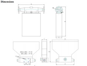
Dimensions Table
| Specs | Line Sizes (mm) |
Fitting Options (mm) | Number and Hole Diameter of Flange join or Screw join (mm) |
Weight KG |
|||
| A | B | C | D | ||||
| DN1 | 1 | 193 | 200 | 75 | 234 | M12×1.5 Screw join | 4 |
| DN3 | 3 | 193 | 225 | 75 | 288 | M12×1.5 Screw join | 4.5 |
| DN6 | 6 | 214 | 234 | 69 | 328 | M16×1.5 Screw join | 7.5 |
| DN10 | 10 | 256 | 291 | 73 | 370 | M20×1.5 Screw join | 9 |
| DN15 | 15 | 413 | 503 | 90 | φ65 | 4-φ14 | 15 |
| DN25 | 25 | 473 | 548 | 96 | φ85 | 4-φ14 | 18.5 |
| DN40 | 40 | 522 | 613 | 116 | φ110 | 4-φ18 | 25.5 |
| DN50 | 50 | 597 | 676 | 137 | φ125 | 4-φ18 | 35 |
| DN80 | 80 | 650 | 837 | 175 | φ160 | 8-φ18 | 53.5 |
| DN100 | 100 | 714 | 934 | 198 | φ190 | 8-φ22 | 70 |
| DN150 | 150 | 815 | 1123 | 265 | φ250 | 8-φ26 | 85 |