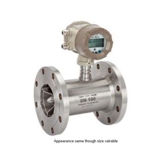
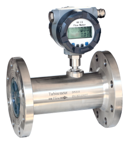
To find out the value of the “K factor” in a turbine flowmeter device, the manufacturer bypasses a defined volume of the liquid via the meter and calculates the pulses produced by the meter. The sum of all pulses divided by the liquid’s known volume provides the “K factor quantity.” For a turbine flowmeter, the “K factor “typifies the equipment. The K factor is linear within a particular acceptance over a restricted flow rate provided as a ratio 10:1 flowrate range. This denotes that the range of flow rate is ten percent of the upper limit.

The producer specifies the upper range, and the lower limit takes ten percent of the upper one, and the acceptance is within a range of between negative and positive 0.5 percent. Specifically, the K factor is not precisely linear within the range of 10:1, although it will not exceed 0.5 percent of the producer’s value. The low range exists simply because, at lower rates, the Reynolds value is found within the laminar range, which is featured by a profile of a parabolic rate in the pipe.

In the middle of the pipe, the liquid has a higher flow rate than the edges, which leads to an inconsistent “K factor” within the range of zero to ten percent of the flow rate. An inductive proximity device calculates the number of pulses in the meter. The propeller consists of several high permeability blades made of steel. The inductive proximity device can monitor each rotor as it passes through the meter to offer the pulse rate.

where Q is the volumetric flow rate (m3/s, l/min, etc.)
G is the unit of time for the flowrate (e.g. multiply by 60 for flow rate per minute)
f is the frequency or number of pulses per second (Hz or 1/s)
K is the pulses per unit volume taken from the K factor (pulses/m3, pulses/liter, etc.)
