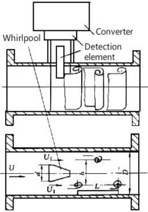
The vortex flowmeter consists of two parts: a sensor and a converter. The sensor includes a vortex generator (bluff body), detection elements, meter body, etc.; the converter includes a preamplifier, filter shaping circuit, D/A conversion circuit, and output interface Circuits, terminals, brackets, and protective covers, etc. In recent years, intelligent flowmeters have also installed microprocessors, display communication, and other functional modules in the converter.

Vortex generator The vortex generator is the main component of the detector. It is closely related to the flow characteristics (meter coefficient, linearity, range, etc.) and resistance characteristics (pressure loss) of the instrument. The requirements for it are as follows.
- The vortex can be controlled to separate synchronously in the axis direction of the vortex generator;
- In a wide range of Reynolds number, there is a stable vortex separation point, keeping a constant Strouhal number;
- Strong vortex street can be generated and the signal to noise ratio is high;
- Simple shape and structure, convenient for processing and standardization of geometric parameters, as well as the installation and combination of various detection elements;
- The material should meet the requirements of fluid properties, corrosion resistance, abrasion resistance, and temperature change;
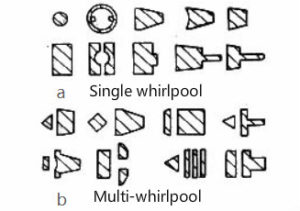
- The natural frequency is outside the frequency band of the vortex signal. has developed a variety of vortex generators, which can be divided into single vortex generators and multiple vortex generators, as shown in Figure 4.
The basic shapes of the single vortex generator are cylindrical, rectangular column, and triangular column, and other shapes are all deformations of these basic shapes.
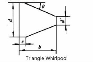
The triangular cylindrical vortex generator is the most widely used one, as shown in Figure 5.
In the figure, D is the gauge diameter.
In order to improve the strength and stability of the vortex street, a multi-vortex generator can be used, but its application is not universal.


d/D=0.2~0.3;c/D=0.1~0.2;
b/d=1~1.5;θ=15o~65o
There are 5 ways for the flowmeter to detect the vortex signal.
- Directly detect the differential pressure on both sides of the vortex generator with the detection element set in the vortex generator;
- A pressure guiding hole is opened on the vortex generating body, and a detection element is installed in the guiding pressure hole to detect the differential pressure on both sides of the generating body;
- Detect the alternating circulation around the vortex generator;
- Detect the alternating differential pressure on the back of the vortex generator;
- Detect the vortex train in the wake.
