
Vortex flowmeters are widely used for measuring steam, gases, and low-viscosity liquids in industrial applications. They are popular because of their simple mechanical construction, relatively low maintenance requirements, and reliable performance under suitable operating conditions.
However, one common problem frequently occurs in industrial plants:
A vortex flowmeter works accurately at normal flow rates but becomes unstable, inaccurate, or even displays zero when the flow rate decreases.
Some operators attempt to solve this problem by increasing sensor sensitivity, adjusting filtering parameters, or recalibrating the instrument. Unfortunately, these adjustments do not always solve the underlying issue.
The reason is that vortex flowmeters have physical measurement limitations at low flow rates.
Understanding these limitations is essential for proper instrument selection, installation, commissioning, and troubleshooting.
This article explains the five major causes of poor low-flow measurement performance and provides practical engineering solutions.
1. How Does a Vortex Flowmeter Work?
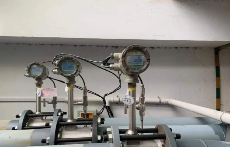
A vortex flowmeter operates according to the Karman vortex street principle.
When a fluid flows past a bluff body installed inside a pipeline, alternating vortices are generated downstream of the obstruction.
The vortex shedding frequency is related to the velocity of the flowing fluid.
Under suitable operating conditions, the relationship can be expressed as:
f = St * v / d_eff
Where:
- f = Vortex shedding frequency (Hz)
- St = Strouhal number
- v = Average fluid velocity (m/s)
- d_eff = Effective characteristic dimension of the vortex-generating body (m)
The effective dimension accounts for the relationship between pipeline velocity and local velocity around the bluff body.
Within the manufacturer’s specified operating range, the Strouhal number remains sufficiently stable for the vortex shedding frequency to be approximately proportional to flow velocity.
The volumetric flow rate is then calculated using the calibrated meter factor:
Q = f / K
Where:
- Q = Actual volumetric flow rate (m3/s)
- f = Vortex shedding frequency (Hz)
- K = Meter factor (pulses/m3)
The units of flow rate and meter factor must be consistent. If the flow rate is expressed in m3/h, the conversion from seconds to hours must be included.
The key point is that a vortex flowmeter determines flow from the frequency of vortex shedding rather than directly measuring fluid velocity.
1.1 Frequency and Signal Strength Are Not the Same
Although vortex shedding frequency is approximately proportional to flow velocity, the fluctuating hydrodynamic force associated with vortex shedding follows a different relationship:
F_L = C_L * rho * v^2 * A / 2
Where:
- F_L = Characteristic fluctuating lift force (N)
- C_L = Lift coefficient
- rho = Fluid density (kg/m3)
- v = Fluid velocity (m/s)
- A = Reference area (m2)
For otherwise comparable conditions, when velocity decreases to half its original value, the characteristic lift force decreases to approximately one-quarter.
When velocity decreases to one-fifth, the force decreases to approximately one twenty-fifth.
This relationship helps explain why detecting vortices becomes increasingly difficult at low flow rates.
However, the actual electrical signal amplitude also depends on sensor construction, mechanical coupling, fluid properties, and signal-processing technology.
A vortex flowmeter may still generate vortices at low flow, but the corresponding sensor signal can become too weak to distinguish reliably from background noise.
2. Five Major Causes of Poor Accuracy at Low Flow Rates
Low-flow measurement problems generally result from several interacting factors rather than one single defect.
2.1 Weak Vortex Signals at Low Fluid Velocity
One of the most important limitations is the reduction in vortex-induced signal strength.
As flow velocity decreases, the fluctuating forces generated by vortex shedding become weaker.
For a simplified comparison:
- At 100% velocity, relative characteristic lift force is 100%.
- At 50% velocity, relative characteristic lift force is approximately 25%.
- At 20% velocity, relative characteristic lift force is approximately 4%.
- At 10% velocity, relative characteristic lift force is approximately 1%.
These values illustrate the approximate quadratic force relationship, not a universal calibration curve for sensor output.
At low velocities, the actual vortex signal may become comparable to mechanical vibration from pumps or compressors, electrical interference, pressure pulsations, and electronic background noise.
When the signal-to-noise ratio becomes too low, the transmitter may fail to identify the vortex shedding frequency correctly.
The result may be an unstable indication, intermittent signal loss, or zero flow output.
This problem is particularly important when measuring low-density gases at low operating pressures.
2.2 Reynolds Number Falls Below the Reliable Measurement Range
The Reynolds number describes the relationship between inertial and viscous forces in flowing fluids.
It is calculated as:
Re = rho * v * D / mu
Where:
- Re = Reynolds number
- rho = Fluid density (kg/m3)
- v = Average fluid velocity (m/s)
- D = Internal pipeline diameter (m)
- mu = Dynamic viscosity (Pa.s)
The Reynolds number decreases when fluid velocity or density decreases, or when dynamic viscosity increases, assuming other variables remain unchanged.
Vortex flowmeters depend on sufficiently stable vortex shedding behavior.
Within the specified Reynolds number range, the relationship between frequency and flow rate can remain predictable.
Outside this range, changes in vortex formation and the Strouhal number may introduce measurement nonlinearity.
Importantly, there is no universal Reynolds number threshold applicable to every vortex flowmeter.
Some designs can detect flow at Reynolds numbers where their stated accuracy is not yet guaranteed. Other models have different minimum limits depending on sensor technology, meter size, and the fluid being measured.
Engineers must distinguish between three operating limits:
- The minimum detectable flow rate.
- The minimum flow rate for guaranteed accuracy.
- The minimum flow rate required by the process.
These three values are not necessarily the same.
2.3 Low Vortex Frequency Affects Measurement Stability
As the flow rate decreases, the vortex shedding frequency also decreases.
For example, suppose a transmitter receives a frequency of 10 Hz.
During a one-second counting interval, approximately 10 pulses are available.
If the frequency decreases to 1 Hz, only approximately one pulse is available during the same interval.
In a simple fixed-window pulse-counting system, such a low pulse count introduces significant resolution limitations.
Modern transmitters may use period measurement, adaptive sampling, digital filtering, or other advanced processing methods to improve low-frequency performance.
Nevertheless, low-frequency measurements can still involve a trade-off between indication stability and response time.
Increasing the averaging or damping time may improve display stability, but it can also delay the response to real flow changes.
This becomes important in applications involving flow control valves, rapidly changing loads, or process control loops.
2.4 Mechanical Vibration and Process Noise Interfere with Vortex Detection
Vortex flowmeters are sensitive to certain types of mechanical vibration because the sensor must distinguish vortex-induced oscillations from unwanted disturbances.
Common interference sources include:
- Pumps and compressors
- Pipe resonance
- Reciprocating machinery
- Pressure pulsations
- Control valves installed too close to the meter
- Inadequate pipeline support
- Electromagnetic interference affecting the signal system
Interference becomes particularly problematic when its frequency overlaps the expected vortex shedding frequency.
However, interference amplitude, frequency, mechanical coupling, and signal-processing characteristics all affect the severity of the problem.
Some modern vortex flowmeters employ dual-sensor arrangements or advanced digital signal processing to reduce vibration-related interference.
Even with these technologies, sufficient signal strength and proper installation remain essential.
At normal flow rates, the vortex signal may be strong enough to overcome background disturbances.
At low flow rates, the same disturbance can become significant compared with the useful signal.
This explains why an instrument may operate correctly at one installation location but perform poorly at another.
2.5 Low Flow Cutoff Settings Cause the Display to Show Zero
Many vortex flowmeters include a Low Flow Cutoff function.
This function forces the flow indication or output to zero when the calculated flow falls below a configured threshold.
Its purpose is to prevent unwanted flow indication caused by weak or unreliable signals and background disturbances.
For example:
- Configured low flow cutoff: 10 m3/h
- Actual process flow: 8 m3/h
- Displayed flow: 0 m3/h
The transmitter may display zero even though fluid is physically moving through the pipeline.
Depending on the instrument, the low-flow cutoff may act on displayed flow, analog output, pulse output, or totalization in different ways.
Some transmitters also incorporate hysteresis to avoid continuous switching around the threshold.
However, lowering the cutoff does not automatically improve the physical measurement capability.
If the actual flow is below the meter’s reliable measurement limit, adjusting the cutoff may simply allow unstable or inaccurate readings to appear.
The correct cutoff value must be determined from the manufacturer’s specified measurement limits and the process requirements.
3. Why Low-Density Gases Are Particularly Difficult to Measure
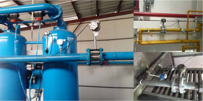
Fluid density is an important factor in vortex flowmeter performance.
Because vortex-induced forces are related to fluid density and velocity, lower-density fluids generally produce weaker detection forces at the same flow velocity.
For example:
- Water density at ordinary conditions: approximately 1,000 kg/m3
- Air density near atmospheric pressure and room temperature: approximately 1.2 kg/m3
This substantial density difference helps explain why low-pressure gas measurement can be more difficult than water measurement at similar velocities.
For gases, operating pressure also affects density.
Increasing gas pressure at otherwise comparable conditions generally increases density, which can improve the strength of the vortex signal.
This is one reason why the minimum measurable flow of a gas vortex flowmeter may vary significantly with operating pressure.
When selecting a vortex flowmeter for gas applications, engineers should always provide:
- Gas composition
- Minimum, normal, and maximum flow rates
- Operating pressure
- Operating temperature
- Gas density or sufficient information to calculate it
- Pipe size and connection requirements
The distinction between actual and standard volumetric flow is particularly important.
A flow rate expressed in Nm3/h or Sm3/h must not be treated as if it were directly equivalent to m3/h at operating conditions.
4. Engineering Example: Why a DN50 Vortex Flowmeter May Fail at Low Flow
Consider a DN50 pipeline carrying compressed air.
For illustration, assume the following operating conditions:
- Internal pipe diameter: 0.0525 m
- Operating pressure: 6 bar(g)
- Operating temperature: 25 deg C
- Approximate air density: 8.2 kg/m3
- Dynamic viscosity: 0.0000185 Pa.s
- Minimum actual volumetric flow: 5 m3/h
These values are illustrative and do not represent the guaranteed performance of a particular vortex flowmeter.
Step 1: Calculate the Pipe Cross-Sectional Area
Formula:
A = 3.1416 * D^2 / 4
Calculation:
A = 3.1416 * 0.0525^2 / 4
A = 0.002165 m2
Step 2: Calculate Flow Velocity
Formula:
v = Q / (3600 * A)
Calculation:
v = 5 / (3600 * 0.002165)
v = 0.64 m/s
Step 3: Calculate Reynolds Number
Formula:
Re = rho * v * D / mu
Calculation:
Re = 8.2 * 0.64 * 0.0525 / 0.0000185
Re = approximately 14,900
The calculated Reynolds number is approximately 14,900.
This does not automatically mean that every vortex flowmeter will fail at this operating point.
However, the flow velocity is relatively low for a conventional vortex flowmeter measuring gas.
The engineer must check the actual minimum measurable velocity and Reynolds number requirements of the proposed instrument.
If the manufacturer specifies a minimum gas velocity above 0.64 m/s for these operating conditions, the instrument cannot be expected to provide reliable measurement at 5 m3/h.
Step 4: Evaluate Possible Solutions
Potential solutions include:
- Selecting a smaller meter size, subject to pressure loss and maximum flow verification.
- Selecting a vortex flowmeter specifically designed for lower flow rates.
- Using a thermal mass flowmeter if the gas application and measurement requirements are suitable.
- Selecting another measurement technology if the required turndown exceeds the vortex meter’s capabilities.
Simply increasing sensor sensitivity is not a substitute for proper instrument selection.
5. How to Select the Correct Vortex Flowmeter Size
Incorrect sizing is one of the most common causes of poor low-flow performance.
A frequent mistake is selecting the meter solely according to the existing pipeline diameter.
For example, a customer may request a DN100 vortex flowmeter because the pipeline is DN100.
However, if the actual flow rate is relatively low, the fluid velocity inside the meter may fall below its reliable measurement range.
5.1 Always Check Three Flow Rates
Before selecting a meter, obtain:
- Qmin: Minimum operating flow rate
- Qnormal: Normal operating flow rate
- Qmax: Maximum operating flow rate
The selected instrument should reliably cover the complete required flow range.
Engineers should verify:
- Minimum flow is above the manufacturer’s guaranteed measurement limit.
- Normal flow is within the recommended operating range.
- Maximum flow is below the allowable velocity and flow limits.
- Reynolds number is within the specified performance range.
- Pressure loss is acceptable for the process.
- Fluid properties are compatible with the meter design.
- Required accuracy can be achieved throughout the operating range.
5.2 Should You Reduce the Flowmeter Diameter?
A smaller meter size can sometimes improve low-flow measurement by increasing velocity through the measuring section.
However, downsizing must be evaluated carefully.
Excessive velocity may increase pressure loss, mechanical stress, vibration, erosion, or other process risks.
The final meter size should satisfy both minimum and maximum operating conditions.
The correct sizing principle is to select the flowmeter according to the complete operating flow range, not simply the nominal pipeline diameter.
6. Installation Requirements for Reliable Low-Flow Measurement
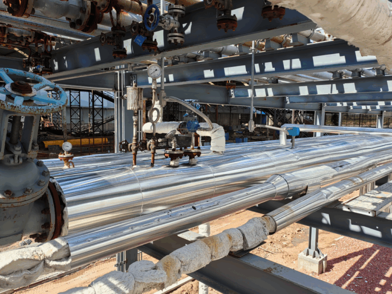
Even a correctly selected vortex flowmeter can perform poorly if the installation conditions are unsuitable.
6.1 Provide Sufficient Straight Pipe Length
Vortex flowmeters require suitable upstream flow conditions.
Elbows, valves, reducers, and other fittings can distort the velocity profile and affect vortex formation.
Straight-run requirements vary by manufacturer and disturbance type.
As a general engineering reference, some installations use 10D to 20D upstream and approximately 5D downstream.
More severe upstream disturbances may require considerably longer straight runs.
These values are not universal installation specifications.
Always follow the instructions for the specific model, particularly when reducers, multiple elbows, control valves, or flow conditioners are involved.
6.2 Minimize Mechanical Vibration
Avoid locations with severe vibration whenever possible.
Provide appropriate pipeline supports and avoid transferring excessive pipe stress into the meter body.
Where necessary, consider instruments equipped with vibration compensation or specialized signal-processing technology.
Changing the installation orientation may help in certain situations, but only when permitted by the manufacturer’s instructions and process requirements.
6.3 Maintain Suitable Process Conditions
For liquid applications, ensure the measuring pipe remains completely filled and avoid entrained gas where possible.
For steam applications, provide proper drainage and prevent condensate accumulation or water hammer.
For gas applications, evaluate pressure pulsations, liquid carryover, and flow disturbances.
Vortex flowmeters generally perform best with suitable single-phase fluids under stable flow conditions.
6.4 Follow Electrical Installation Requirements
Proper wiring and grounding help minimize interference.
Use the recommended signal cables, shielding arrangements, and grounding methods.
Keep signal wiring appropriately separated from high-power electrical cables.
For remote-mounted electronics, respect the manufacturer’s cable length and installation limitations.
Do not assume that one grounding arrangement applies to every transmitter model.
7. Low Flow Cutoff, Filtering, and Signal Adjustment
When low-flow performance is unstable, commissioning parameters should be examined systematically.
7.1 Verify the Low Flow Cutoff
First, confirm whether the actual flow rate is above the manufacturer’s specified minimum measurable flow.
Then inspect the configured cutoff value.
The cutoff should not unnecessarily suppress a flow rate that the instrument can reliably measure and that the process requires.
However, setting the cutoff below the physical measurement capability does not make the instrument more accurate.
7.2 Check Sensor Sensitivity and Trigger Settings
Some vortex transmitters allow sensitivity or trigger thresholds to be adjusted.
Increasing sensitivity may improve the detection of weak vortex signals.
However, excessive sensitivity can also increase susceptibility to mechanical vibration and background noise.
Adjust these parameters only in accordance with the transmitter manufacturer’s instructions.
7.3 Configure Filtering Carefully
Digital filtering can reduce unwanted fluctuations.
However, selecting an excessively low cutoff frequency may suppress valid vortex signals.
The appropriate filter setting depends on the expected shedding frequency, signal characteristics, and transmitter design.
Avoid using one fixed filter frequency for all liquids, gases, and steam applications.
7.4 Adjust Damping Time
Increasing damping time can stabilize the displayed flow value.
However, this introduces a slower response to actual flow changes.
For process control applications, excessive damping may negatively affect control-loop performance.
The damping setting should provide an appropriate balance between measurement stability and response speed.
7.5 Check the Meter Factor and Compensation Settings
Verify that the configured K-factor corresponds to the calibrated meter.
For gas and steam applications, also check whether pressure and temperature compensation is necessary for the required output quantity.
A vortex flowmeter fundamentally measures actual volumetric flow.
If mass flow or standardized volumetric flow is required, appropriate fluid-property calculations and compensation may be necessary.
8. Troubleshooting Common Low-Flow Problems
Problem 1: Flow Exists but the Display Shows Zero
Possible causes:
- Actual flow is below the minimum measurable flow rate.
- Low flow cutoff is configured too high.
- Vortex signals are too weak for reliable detection.
- Signal filtering or trigger settings are inappropriate.
Recommended actions:
Check the actual flow rate, minimum measurable flow specification, and low flow cutoff settings.
If the actual flow is below the reliable measurement range, consider resizing the meter or selecting another technology.
Problem 2: Flow Reading Fluctuates at Low Flow Rates
Possible causes:
- Weak vortex signals.
- Mechanical vibration.
- Pressure pulsations.
- Unstable flow conditions.
- Inadequate upstream straight pipe length.
Recommended actions:
Inspect the installation conditions, mechanical supports, and transmitter diagnostic information.
Check whether the vibration frequency overlaps the vortex shedding frequency.
Problem 3: The Flowmeter Shows Flow When the Pipeline Is Stopped
Possible causes:
- Mechanical vibration.
- Electrical interference.
- Incorrect trigger settings.
- Actual leakage or unintended flow.
Recommended actions:
Confirm that the pipeline is fully isolated and that no real flow exists.
Inspect grounding, shielding, vibration sources, and transmitter settings.
Problem 4: Low-Flow Readings Are Consistently Inaccurate
Possible causes:
- Reynolds number outside the guaranteed performance range.
- Incorrect meter sizing.
- Incorrect K-factor.
- Incorrect fluid density or compensation settings.
Recommended actions:
Calculate the operating Reynolds number and verify the manufacturer’s measurement limits.
Check the configured meter factor and compensation parameters.
Problem 5: The Flowmeter Responds Too Slowly
Possible causes:
- Excessive damping.
- Excessive filtering.
- Long averaging time.
Recommended actions:
Review the response-time settings and ensure they are suitable for the process control requirements.
Problem 6: Accuracy Deteriorates After Extended Operation
Possible causes:
- Deposits on the bluff body.
- Mechanical erosion.
- Sensor deterioration.
- Changes in process conditions.
- Moisture ingress or electrical faults.
Recommended actions:
Inspect the meter, clean the measuring section when appropriate, and verify calibration.
9. When Should You Choose Another Flowmeter Technology?
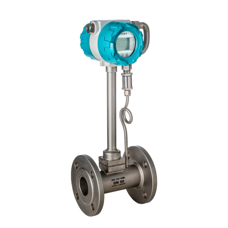
A vortex flowmeter is not always the best solution for applications with very low flow rates or extremely wide operating ranges.
Depending on the fluid and measurement objectives, another flowmeter principle may offer better performance.
9.1 Electromagnetic Flowmeter
Electromagnetic flowmeters are suitable for electrically conductive liquids.
They can be an excellent choice for water, wastewater, and many chemical liquid applications.
However, they are not suitable for non-conductive gases, steam, or most hydrocarbon liquids.
9.2 Thermal Mass Flowmeter
Thermal mass flowmeters are widely used for compressed air and other suitable gas applications.
They can be advantageous for certain low-flow gas measurements.
However, changes in gas composition, contamination, or process conditions may affect measurement performance.
9.3 Coriolis Mass Flowmeter
Coriolis flowmeters directly measure mass flow and can provide high accuracy over a suitable operating range.
They are useful in chemical processing, fuel measurement, and applications requiring accurate mass measurement.
However, pressure loss, instrument size, installation requirements, and investment cost must be considered.
9.4 Ultrasonic Flowmeter
Ultrasonic flowmeters can be suitable for various liquid applications.
Clamp-on ultrasonic flowmeters offer non-intrusive installation, which can be attractive for existing pipelines.
Their performance depends on fluid properties, flow conditions, pipe characteristics, and installation quality.
9.5 Positive Displacement Flowmeter
Positive displacement flowmeters, including oval gear flowmeters, are suitable for certain clean liquid applications.
They can offer good measurement performance for some higher-viscosity liquids.
However, pressure loss, moving components, and maintenance requirements should be evaluated.
The best flowmeter is not necessarily the one with the highest advertised accuracy. It is the one that can reliably meet the actual process requirements.
10. Frequently Asked Questions
Q1. Why does a vortex flowmeter display zero when fluid is still flowing?
The actual flow may be below the instrument’s minimum measurable flow rate, or the configured low flow cutoff may be suppressing the indication.
Weak vortex signals, insufficient Reynolds number, or inappropriate filtering can also contribute.
Q2. Can increasing sensitivity improve low-flow accuracy?
It may improve signal detection in some applications, but it cannot eliminate the physical limitations of vortex shedding.
Excessive sensitivity can also increase false flow indications caused by vibration or noise.
Q3. Is 20% of full-scale flow the universal accuracy limit?
No.
Some instruments can maintain their specified accuracy below 20% of their maximum rated flow, while others may have higher minimum requirements under certain operating conditions.
Always refer to the manufacturer’s accuracy and minimum flow specifications.
Q4. Can a vortex flowmeter measure very low gas flow rates?
It depends on gas density, velocity, pressure, meter size, and sensor technology.
Very low-density, low-velocity gas applications are often challenging for conventional vortex flowmeters.
Q5. Does reducing the meter diameter always improve accuracy?
No.
Reducing meter diameter increases velocity at a given actual volumetric flow rate, which may improve low-flow detection.
However, it may also increase pressure loss and cause excessive velocity at maximum flow.
Both operating extremes must be checked.
Q6. Can recalibration solve poor low-flow performance?
Recalibration may correct certain measurement-factor errors within the instrument’s valid operating range.
It cannot reliably restore measurement performance when vortex shedding becomes unsuitable or the sensor signal falls below the detection capability.
Q7. What information is needed to select a vortex flowmeter?
The essential information includes:
- Fluid type and composition
- Minimum, normal, and maximum flow rates
- Operating pressure and temperature
- Pipeline diameter
- Required accuracy
- Installation conditions
- Output signals and communication requirements
For gas and steam measurement, the required flow units and compensation requirements must also be clearly specified.
11. Conclusion
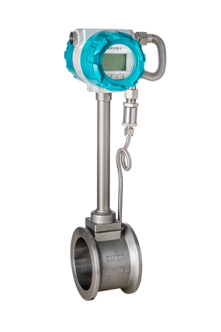
Vortex flowmeters are reliable instruments when applied within their specified operating conditions.
However, low-flow measurement performance can deteriorate because of five major factors:
- Reduced vortex-induced signal strength.
- Reynolds number limitations.
- Low-frequency measurement challenges.
- Mechanical vibration and process interference.
- Low flow cutoff and signal-processing settings.
These factors may occur individually or simultaneously.
The most effective solution is not simply to increase transmitter sensitivity or change filtering parameters.
Reliable low-flow measurement begins with correct engineering selection.
Before ordering a vortex flowmeter, engineers should verify the minimum, normal, and maximum flow rates, operating fluid density, Reynolds number, pipeline conditions, and required measurement accuracy.
If the required minimum flow is outside the instrument’s guaranteed measurement range, consider resizing the meter or selecting another flow measurement technology.
At Zero Instrument, we recommend evaluating the complete operating conditions before selecting a vortex flowmeter for steam, gas, or liquid applications.
A properly selected and installed flowmeter provides better measurement reliability, reduces troubleshooting time, and minimizes long-term operating costs.
Need help selecting a vortex flowmeter for your application?
Contact Zero Instrument with your fluid type, pipeline size, operating pressure, temperature, and flow range. Our team can help evaluate suitable measurement solutions for your application.
Website: https://zeroinstrument.com