
Magnetic level gauges are widely used for liquid level indication in chemical plants, oil storage facilities, water treatment systems, and other industrial processes. Their simple mechanical design, local visual indication, and ability to operate without an external power supply make them a practical solution for many storage tanks and process vessels.
However, not every magnetic level gauge performs reliably in every application.
Some gauges develop leakage after a relatively short operating period. Others suffer from stuck floats, incorrect level indication, corrosion, or damaged indicator components.
These problems are often blamed on poor product quality. In reality, many premature failures can be traced to improper instrument selection, unsuitable materials, incorrect installation, or operating conditions that were not fully considered during procurement.
Selecting a magnetic level gauge involves much more than specifying the measuring range and flange size.
This article explains four critical factors that engineers and procurement professionals should evaluate before purchasing a magnetic level gauge.
1. Understanding How a Magnetic Level Gauge Works
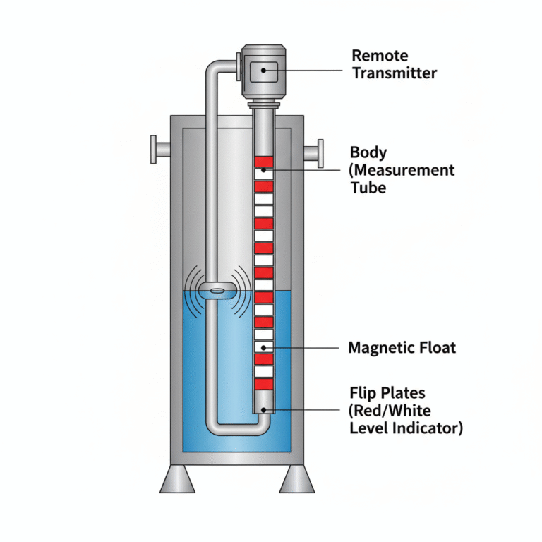
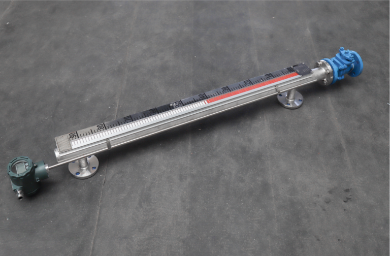
A magnetic level gauge, also known as a magnetic level indicator (MLI) or magnetic flap level gauge, uses a float containing a permanent magnet to indicate the liquid level inside a vessel.
The instrument typically consists of:
- An external measuring chamber connected to the vessel.
- A magnetic float that moves with the liquid level.
- An external indicator containing magnetic flaps or rollers.
- Process connections, isolation valves, and optional drain or vent connections.
- Optional magnetic switches or continuous level transmitters.
As the liquid level rises or falls, the float moves inside the measuring chamber. Its magnetic field activates the external indicator, providing a visible indication of the liquid level without direct contact between the process liquid and the display.
Because the indicating mechanism is magnetically coupled, the external display does not require a conventional transparent sight glass exposed directly to process pressure.
Nevertheless, the measuring chamber, float, process connections, and sealing components must withstand the actual operating conditions.
The reliability of a magnetic level gauge depends on selecting the correct float, wetted materials, pressure rating, and installation configuration.
2. Factor One: Liquid Density and Viscosity
2.1 Why liquid density matters
A magnetic level gauge relies on buoyancy to keep the float partially submerged in the process liquid.
The buoyant force acting on the float can be expressed as:
F = ρ × g × V
Where:
- F = buoyant force (N)
- ρ = liquid density (kg/m³)
- g = gravitational acceleration (m/s²)
- V = displaced liquid volume (m³)
For the float to operate correctly, the buoyant force must balance its weight while allowing the magnet to remain at the intended indication position.
When the liquid density decreases, the float generally becomes more deeply submerged.
If the density falls below the float’s design limit, the float may fail to operate correctly or may sink.
This is particularly important for applications involving:
- Liquefied petroleum gas (LPG)
- Liquid ammonia
- Light hydrocarbons
- Low-density chemical liquids
- Liquids with significant density variations caused by temperature changes
For example, a float designed for water may not operate correctly in a low-density hydrocarbon.
Some specially designed magnetic level gauges can accommodate liquids with densities around 0.45 g/cm³ or lower, depending on the product design. However, this is not a universal minimum density requirement.
Selection recommendation: Always provide the liquid density at the actual operating temperature and pressure. The manufacturer should confirm the appropriate float design and minimum operating density.
2.2 How viscosity affects float movement
Liquid viscosity is another important selection parameter.
In high-viscosity applications, the float may experience greater resistance as it moves through the measuring chamber.
Typical challenging applications include:
- Heavy fuel oil
- Resin
- Molasses
- High-viscosity chemical products
- Certain lubricating oils
- Liquids that thicken or solidify at low temperatures
High viscosity can cause delayed float response, while deposits or solidification may cause the float to become stuck.
However, there is no single maximum viscosity value that applies to all magnetic level gauges.
Some designs may be suitable for relatively viscous fluids, while others require special configurations.
For temperature-sensitive liquids, a jacketed measuring chamber or suitable heat tracing may be necessary to maintain adequate fluidity.
Heating arrangements must be designed to avoid overheating the instrument or exceeding its temperature limits.
Selection recommendation: Specify the viscosity at operating temperature, not only at room temperature. For fluids that crystallize, polymerize, or solidify, evaluate whether heating, cleaning provisions, or an alternative measurement technology is needed.
3. Factor Two: Wetted Materials and Chemical Compatibility
3.1 Why material selection is critical
Corrosion is one of the most serious causes of premature magnetic level gauge failure.
An unsuitable material can lead to:
- Pitting corrosion
- Crevice corrosion
- General wall thinning
- Leakage from the measuring chamber
- Float corrosion or damage
- Loss of mechanical integrity
A common mistake is assuming that stainless steel is suitable for every industrial liquid.
Although 304 and 316L stainless steel provide good corrosion resistance in many applications, they are not universally compatible with aggressive chemicals.
For example, using standard stainless steel for hydrochloric acid service can result in severe corrosion.
Similarly, 316L stainless steel may suffer from pitting or crevice corrosion in chloride-rich environments, especially at elevated temperatures.
3.2 Typical material selection considerations
| Process medium | Materials to consider |
|---|---|
| Clean water and diesel | 304 or 316L stainless steel |
| General industrial water | 304 or 316L, depending on water chemistry |
| Seawater or high-chloride liquids | Suitable duplex stainless steel, titanium, or compatible nonmetallic lining |
| Hydrochloric acid | Compatible fluoropolymer lining or other specially selected corrosion-resistant materials |
| Strong alkaline solutions | Materials selected according to concentration and temperature |
| Organic solvents | Materials verified against the specific solvent composition |
| High-temperature thermal oil | Suitable metallic chamber, seals, and float designed for the operating temperature |
Note: This table provides preliminary selection guidance only. Final material compatibility must be verified using the exact chemical composition, concentration, temperature, pressure, and applicable corrosion data.
3.3 PTFE-lined magnetic level gauges
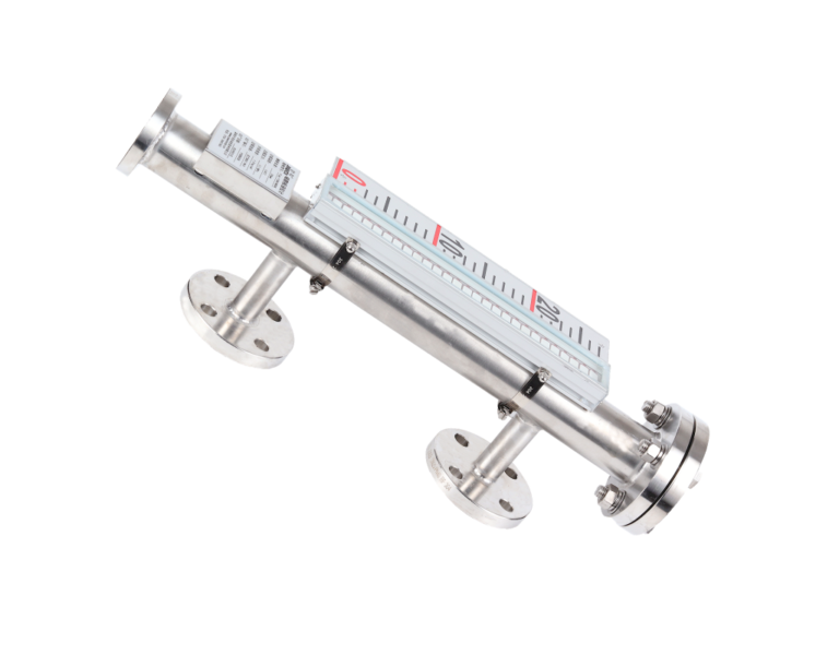
For highly corrosive applications, a magnetic level gauge with a suitable fluoropolymer-lined measuring chamber may be considered.
PTFE offers excellent resistance to many aggressive chemicals and is widely used in corrosion-resistant process equipment.
However, engineers should pay attention to the following:
Temperature limits: The allowable service temperature depends on the complete lined instrument design, not merely the nominal temperature resistance of PTFE.
Pressure and vacuum conditions: The lining must be mechanically suitable for the operating pressure, vacuum conditions, and temperature cycling.
Float compatibility: The float material must also resist the process liquid.
Process connections: The flange lining, gaskets, drain fittings, and other wetted components require the same level of chemical compatibility.
A corrosion-resistant measuring chamber alone does not guarantee that the entire instrument is suitable for a corrosive process.
3.4 Do not overlook the float material
Even when the measuring chamber is manufactured from an appropriate material, an incompatible float can still fail.
The float is continuously exposed to the process fluid and must satisfy several requirements simultaneously:
- Corrosion resistance
- Adequate buoyancy
- Mechanical strength
- Pressure resistance
- Temperature resistance
- Stable magnetic performance
Special float materials or constructions may be required for low-density, high-pressure, or highly corrosive applications.
Selection recommendation: Request confirmation of all wetted materials, including the chamber, float, process connections, gaskets, and drain components.
4. Factor Three: Operating Pressure and Temperature
4.1 Pressure rating must match the process conditions
A magnetic level gauge is effectively an external pressure-containing chamber connected to the process vessel.
Therefore, its pressure rating must be appropriate for the specified design conditions.
Industrial magnetic level gauges are available in configurations for atmospheric tanks as well as high-pressure process vessels.
Certain specially engineered models can withstand pressures reaching tens of megapascals. However, maximum pressure ratings vary significantly between manufacturers and instrument designs.
It is incorrect to assume that a standard magnetic level gauge can withstand 32 MPa simply because another model in the same product category has that rating.
Engineers should confirm:
- Normal operating pressure
- Maximum operating pressure
- Design pressure
- Possible vacuum conditions
- Hydrostatic and other specified pressure tests
- Applicable design codes and project requirements
The pressure capability of the complete instrument must be evaluated, including the chamber, float, welded joints, end closures, and process connections.
4.2 High-temperature applications require special attention
Temperature affects both the mechanical strength and operating performance of magnetic level gauges.
At elevated temperatures, the following factors become particularly important:
Chamber material: Material strength and allowable stress vary with temperature.
Float construction: The float must withstand the combined pressure and temperature conditions without deformation or collapse.
Indicator protection: Excessive heat may damage external magnetic indicators or associated components.
Sealing materials: Gaskets and seals must be suitable for the operating temperature and fluid.
Thermal expansion: Long measuring chambers may require appropriate allowances for thermal expansion.
High-temperature gauges may use insulation arrangements, heat-dissipating structures, or specially designed indicator assemblies.
Some specialized instruments are designed for operating temperatures approaching 450°C. Such ratings must be confirmed for the exact model and configuration.
4.3 Long measuring chambers and mechanical support
Long magnetic level gauges require careful mechanical design.
As the measuring length increases, engineers must consider:
- Chamber weight
- Structural rigidity
- Thermal expansion
- Equipment vibration
- External piping loads
- Installation and maintenance accessibility
Additional supports or segmented construction may be appropriate for some applications.
However, the need for additional support should be determined by engineering calculations and manufacturer recommendations rather than by applying one universal length limit.
Selection recommendation: Always specify design pressure and design temperature in addition to normal operating conditions. For high-pressure, high-temperature, or unusually long instruments, request dimensional drawings and relevant design documentation before ordering.
5. Factor Four: Installation Configuration and Measurement Dead Zones
5.1 Side-mounted magnetic level gauges
Side-mounted magnetic level gauges are commonly installed on storage tanks and process vessels with suitable upper and lower process connections.
The measuring chamber is connected to the vessel, allowing the liquid level in the chamber to follow the level in the tank when the connections are unobstructed and the pressures are appropriately balanced.
Typical applications include:
- Chemical storage tanks
- Oil storage vessels
- Water treatment tanks
- Pressure vessels
- Process separators
For side-mounted instruments, the distance between the process connection centers is an important dimension.
However, the flange center-to-center distance is not necessarily the same as the usable measuring range.
Engineers must confirm the relationship between connection positions, float travel, and the required level indication range.
5.2 Top-mounted magnetic level gauges
Top-mounted designs can be considered when side connections are unavailable or unsuitable.
Typical applications include:
- Underground storage tanks
- Certain chemical tanks
- Vessels with restricted side access
- Installations where only a top process opening is available
Top-mounted magnetic level gauges may use a float connected through a mechanical guiding or linkage arrangement, depending on the product design.
Compared with standard side-mounted designs, top-mounted instruments may have different requirements for float clearance, insertion length, mechanical guidance, and measuring range.
Therefore, top-mounted and side-mounted configurations should not be treated as interchangeable without evaluating the installation conditions.
5.3 Why vertical installation matters
Magnetic level gauges generally require correct vertical alignment to allow the float to move freely.
If the measuring chamber is installed at an excessive angle, the float may rub against the chamber wall.
Potential consequences include:
- Float sticking
- Sluggish level response
- Incorrect indication
- Increased mechanical wear
The allowable installation deviation depends on the manufacturer’s design.
For reliable operation, installers should follow the specified alignment tolerance rather than assuming that one angular limit applies to all instruments.
5.4 Understanding measurement dead zones
Measurement dead zones are areas near the ends of the instrument where the liquid level cannot be indicated correctly or where full float travel is restricted.
Their dimensions depend on several design characteristics:
- Float length
- Float immersion depth
- Magnet position
- Mechanical stops
- Measuring chamber construction
- Installation configuration
Liquid density can influence float immersion depth and therefore affect the relationship between the actual liquid surface and the indicated level.
However, it is not technically correct to assign one fixed dead-zone dimension to all liquids with the same density.
For example, two magnetic level gauges measuring the same liquid may have different upper and lower dead zones because their floats and chambers are designed differently.
Selection recommendation: Provide the required maximum and minimum visible liquid levels, process connection dimensions, and liquid density. Ask the manufacturer to confirm the actual effective measuring range and dead zones.
6. Why Do Magnetic Level Gauges Leak or Fail Prematurely?
Even a correctly selected instrument can fail if manufacturing quality, installation, or maintenance is inadequate.
Understanding the most common failure mechanisms helps operators prevent unexpected shutdowns.
6.1 Corrosion of the measuring chamber
One of the most serious problems occurs when the chamber material is incompatible with the process liquid.
Localized corrosion can gradually penetrate the chamber wall, resulting in leakage.
Prevention: Verify chemical compatibility and inspect the instrument for early signs of corrosion.
6.2 Leakage from flanges, gaskets, or drain connections
Not all leaks originate from corrosion.
Process connections, flange gaskets, threaded fittings, drain valves, and other sealing points can also develop leakage.
Possible causes include incorrect gasket selection, improper assembly, thermal cycling, vibration, or degraded sealing materials.
Prevention: Use compatible sealing materials, follow appropriate assembly procedures, and conduct required leak tests and inspections.
6.3 Float sticking caused by deposits
Liquids containing suspended solids, crystals, or deposits may accumulate inside the measuring chamber.
Over time, these deposits can restrict float movement.
Prevention: Evaluate contamination and crystallization risks during selection. Where appropriate, provide suitable drain, flushing, or maintenance arrangements.
6.4 Float damage under excessive differential pressure
A magnetic float is typically a sealed component designed for a specified operating pressure.
If the actual pressure conditions exceed its design limits, the float may deform or lose buoyancy.
This can result in incorrect level indication or complete measurement failure.
Prevention: Verify the pressure rating of the float separately from the nominal pressure rating of the chamber.
6.5 Incorrect installation or excessive mechanical stress
Poor piping alignment, inadequate support, vibration, and external mechanical loads can damage connections or affect chamber alignment.
Prevention: Install the instrument according to the manufacturer’s drawings, provide suitable supports where required, and avoid transferring excessive piping loads to the measuring chamber.
6.6 Magnetic indicator malfunction
Sometimes the float moves correctly, but the external magnetic indicator does not respond as expected.
Possible causes include incorrect indicator positioning, damaged magnetic components, or magnetic coupling problems.
Prevention: Inspect the external indicator assembly, verify its alignment, and follow the manufacturer’s maintenance procedure.
7. Explosion Protection and Electrical Accessories
One advantage of a basic magnetic level gauge is that local level indication does not require an external electrical power supply.
However, this does not automatically mean that every magnetic level gauge is suitable for installation in any hazardous area.
Hazardous-area suitability must be evaluated according to the instrument’s construction and the requirements applicable to the installation.
When electrical accessories are added, additional considerations become necessary.
Common accessories include:
- Magnetic level switches
- Reed-chain level transmitters
- 4–20 mA continuous level transmitters
- HART communication modules
- Remote monitoring components
Electrical accessories installed in hazardous areas must have appropriate explosion-protection characteristics and certification where required.
Depending on the installation, suitable protection methods may include intrinsic safety or flameproof enclosures.
The applicable protection concept, equipment group, temperature class, and certification must match the hazardous-area classification and local regulatory requirements.
For intrinsically safe systems, associated apparatus such as suitable barriers or isolators may be required according to the certified system design.
Important: Do not assume that an optional level transmitter or switch has the same hazardous-area approval as the mechanical level gauge assembly.
8. Magnetic Level Gauge Selection Checklist
Before requesting a quotation, engineers should prepare the following information.
| Selection parameter | Required information |
|---|---|
| Process liquid | Name and chemical composition |
| Liquid density | Minimum and maximum density at operating conditions |
| Viscosity | Viscosity at operating temperature |
| Operating pressure | Normal and maximum pressure |
| Design pressure | Required mechanical design pressure |
| Operating temperature | Normal and maximum temperature |
| Design temperature | Required design temperature range |
| Measuring range | Required effective indication range |
| Installation type | Side-mounted or top-mounted |
| Process connection | Size, pressure class, facing, and applicable standard |
| Wetted material | Chamber, float, and lining requirements |
| Electrical accessories | Level switches, 4–20 mA transmitter, HART, etc. |
| Hazardous area | Area classification and required certification |
| Special conditions | Corrosion, crystallization, vibration, insulation, or heat tracing |
Providing complete application information allows the manufacturer to evaluate the appropriate chamber design, float configuration, materials, and accessories.
It also reduces the risk of incorrect quotations, specification changes, and unexpected operating problems.
9. When Is a Magnetic Level Gauge Not the Best Choice?
Although magnetic level gauges are reliable in many industrial applications, they are not suitable for every liquid or operating condition.
Alternative measurement technologies may be more appropriate when:
- The liquid is extremely viscous or prone to solidification.
- Heavy scaling or crystallization frequently occurs.
- The liquid contains significant amounts of sludge or deposits.
- The process requires continuous measurement but local mechanical indication is unnecessary.
- Tank geometry or installation restrictions make external chambers impractical.
- Process conditions exceed the available instrument design limits.
Depending on the application, alternatives may include radar level transmitters, guided wave radar, differential pressure transmitters, or other suitable level measurement technologies.
The final selection should consider fluid properties, process safety, installation constraints, required accuracy, maintenance requirements, and total operating cost.
10. Conclusion
A magnetic level gauge may look like a relatively simple mechanical instrument, but reliable performance depends on correct engineering selection.
Before purchasing, engineers should pay particular attention to four fundamental factors:
- Liquid density and viscosity: Ensure the float can move reliably under actual process conditions.
- Wetted materials and corrosion resistance: Select the chamber, float, seals, and connections based on verified chemical compatibility.
- Pressure and temperature: Confirm the mechanical limits of the complete instrument assembly.
- Installation and measuring range: Check mounting configuration, vertical alignment, process connections, and effective measurement dead zones.
Premature leakage, stuck floats, and incorrect indication are often preventable through proper instrument selection, manufacturing quality control, installation, and maintenance.
The key is to evaluate the complete application instead of choosing a magnetic level gauge based only on price, measuring length, or connection size.
At Zero Instrument, we help customers select magnetic level gauges for industrial storage tanks, chemical processing equipment, and other process applications.
By reviewing liquid properties, operating conditions, material compatibility, and installation requirements, we can recommend suitable instrument configurations for reliable level indication.
Need help selecting a magnetic level gauge?
Visit www.zeroinstrument.com or contact our technical sales team with your application parameters for assistance.
Technical note: The material and application recommendations in this article are general engineering guidance. Final instrument specifications should be confirmed against the manufacturer’s technical documentation, applicable design standards, and actual process conditions.