
Radar level transmitters are widely used in industrial applications, including storage tanks, chemical reactors, wastewater treatment facilities, and process vessels. Their non-contact measurement capability, low maintenance requirements, and suitability for various operating conditions make them a popular choice for continuous level monitoring.
However, unstable level readings remain a common problem in industrial applications.
A typical situation occurs when the actual liquid surface appears relatively stable, but the radar level transmitter displays rapidly changing values. On the PLC or DCS trend screen, the measured level fluctuates continuously, creating a sawtooth-like pattern.
These fluctuations can cause more than just inaccurate readings. In automatic control systems, unstable level signals may lead to frequent control valve adjustments, pump cycling, unnecessary alarms, and even unexpected process shutdowns.
Why does a radar level transmitter produce unstable readings, and how can these problems be resolved effectively?
This article examines the most common causes of radar level fluctuations and provides practical troubleshooting recommendations for instrumentation engineers and maintenance technicians.
1. Understanding Radar Level Measurement Fluctuations
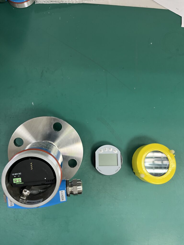
Radar level transmitters measure the distance between the sensor reference point and the material surface using electromagnetic waves.
In conventional non-contact radar level measurement, the transmitter emits microwave signals toward the material surface and receives reflected signals.
The instrument calculates the distance to the surface and converts it into a level measurement based on the configured tank height or reference distance.
Under normal conditions, the measured level should follow actual changes in the liquid surface.
However, if the instrument receives weak, distorted, or unwanted reflections, the calculated level may become unstable.
Typical symptoms include:
- Sudden increases or decreases in measured level.
- Frequent oscillations in the displayed level value.
- Sawtooth-like fluctuations in PLC/DCS trend curves.
- Intermittent measurement loss or incorrect high-level readings.
- Level changes that do not match actual process conditions.
- Unstable control valve or pump operation caused by fluctuating level signals.
It is important to understand that not every fluctuating level signal indicates a defective radar transmitter.
The problem may originate from process conditions, sensor installation, signal processing, electrical interference, or the control system itself.
Identifying the actual source of instability is the first step toward effective troubleshooting.
2. Liquid Surface Turbulence and Agitation
One of the most common causes of unstable radar level measurement is excessive movement of the liquid surface.
This is particularly common in tanks equipped with:
- Mechanical agitators or mixers.
- High-velocity liquid inlets.
- Recirculation pipelines.
- Pump discharge connections.
- Strong internal fluid movement.
- Rapid filling or draining operations.
When the liquid surface is turbulent, radar signals may be reflected in different directions.
As the surface continuously changes shape, the reflected signal amplitude and apparent measurement distance may vary.
Under severe conditions, the radar transmitter may temporarily lose the correct surface echo or switch between different reflections.
This can produce sudden changes in measured level.
Recommended solutions
1. Optimize the radar installation position
Avoid installing the radar transmitter directly above high-velocity filling streams, agitators, or areas with excessive surface movement.
2. Evaluate the use of a stilling well or bypass chamber
In suitable applications, a properly designed stilling well or bypass chamber can reduce the effects of surface turbulence.
However, the installation must allow reliable level equalization and comply with the radar manufacturer’s installation requirements.
3. Adjust the damping time appropriately
Increasing the damping time can reduce the effect of rapid, insignificant fluctuations on the output signal.
However, excessive damping can delay the response to genuine level changes.
4. Verify the actual process conditions
Check whether the fluctuations correspond to pump operation, agitator speed, filling cycles, or other process changes.
If the measured level fluctuations follow a specific operating pattern, process turbulence should be investigated before changing transmitter settings.
3. Foam Interference and Weak Radar Echoes
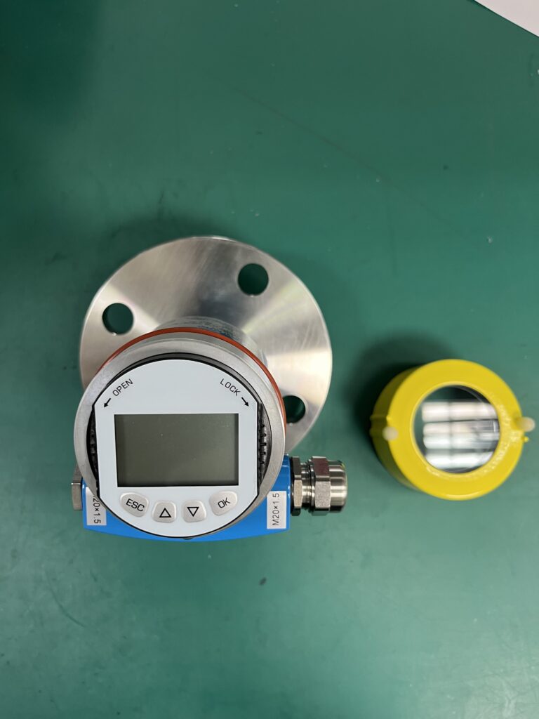
Foam is another important factor affecting radar level measurement.
Foam is frequently encountered in applications involving:
- Wastewater treatment.
- Chemical processing.
- Fermentation.
- Detergent production.
- Mixing and agitation processes.
- Certain food and beverage applications.
Depending on its physical properties, foam may absorb, scatter, attenuate, or reflect radar signals.
The severity of interference depends on several factors, including foam thickness, moisture content, dielectric properties, and radar operating frequency.
In some applications, the radar signal can penetrate the foam and detect the liquid surface.
In other applications, the instrument may receive a weak liquid-surface echo or incorrectly identify a reflection from the foam layer.
Possible symptoms include:
- Unstable level readings.
- Reduced echo signal strength.
- Intermittent loss of measurement.
- Incorrect detection of the foam surface.
- Sudden changes between different apparent liquid levels.
Recommended solutions
Check the echo curve first.
Review the signal amplitude, echo quality, and measurement tracking behavior to determine whether the instrument is detecting the actual liquid surface.
Evaluate the radar technology.
Different radar frequencies and antenna designs behave differently under foaming conditions. Select the appropriate technology based on the actual application and manufacturer recommendations.
Reduce excessive foam generation where practical.
Possible measures include adjusting the filling arrangement, reducing unnecessary agitation, or implementing process-approved foam control methods.
Consider alternative measurement arrangements.
For challenging foaming applications, a guided wave radar, suitable chamber arrangement, or another measurement technology may provide better performance.
However, the suitability of these solutions must be evaluated for the specific process.
A stilling well should not automatically be considered a solution to foam interference because foam may also form or accumulate inside the well.
4. False Echoes from Tank Internals
Radar level transmitters may receive reflections not only from the liquid surface but also from structures inside the tank.
Common sources of unwanted reflections include:
- Agitator blades.
- Heating coils.
- Internal support structures.
- Ladders and reinforcement members.
- Inlet pipes.
- Tank walls.
- Nozzles and other internal obstructions.
These reflections are often called false echoes.
When the actual liquid-surface echo becomes weak, the transmitter may incorrectly identify a false echo as the measurement target.
As a result, the displayed level may jump suddenly or fluctuate between different values.
Example
Consider a radar transmitter installed on a chemical mixing tank.
During normal operation, the instrument detects the liquid surface correctly.
When the agitator starts, moving blades produce additional reflections. At certain positions, the unwanted echoes may become stronger than the actual surface reflection.
If the transmitter’s echo tracking algorithm selects the wrong reflection, the measured level may change abruptly even though the actual liquid level remains relatively constant.
Recommended solutions
1. Inspect the radar echo curve
Identify the actual surface reflection and compare it with reflections from fixed or moving internal structures.
2. Perform false echo suppression when appropriate
Many radar level transmitters offer false echo mapping or interference echo suppression functions.
These functions can help the instrument distinguish known obstructions from the actual liquid surface.
However, false echo suppression must be configured carefully.
Incorrect mapping may suppress the true surface echo, especially if the tank level changes or the mapping is performed under unsuitable conditions.
3. Review the installation position
Avoid locations where major obstructions lie directly in the radar beam.
4. Check antenna alignment and beam angle
Antenna orientation and beam geometry can significantly influence reflections from tank internals.
Important: Never perform aggressive false echo mapping without first understanding the echo curve and the actual tank conditions.
5. Electrical Interference and 4–20 mA Signal Instability
Not all unstable level readings originate from radar measurement problems.
In some installations, the transmitter measures the level correctly, but the signal becomes unstable during transmission to the PLC or DCS.
Electrical interference is especially common in industrial environments with:
- Variable frequency drives (VFDs).
- Large motors.
- High-power electrical equipment.
- Poorly shielded signal cables.
- Improper grounding arrangements.
- Loose terminal connections.
- Unstable instrument power supplies.
Electromagnetic interference may affect analog signal circuits or associated electronic equipment, causing apparent fluctuations in the measured level.
Typical symptoms
- The local transmitter display remains stable while the DCS trend fluctuates.
- The signal becomes unstable when a motor or VFD starts.
- Sudden fluctuations occur during switching operations.
- Measurements improve when nearby electrical equipment is turned off.
Recommended troubleshooting procedure
Step 1: Compare the local transmitter reading with the DCS value.
If the transmitter display remains stable but the DCS reading fluctuates, investigate the signal transmission and control system.
Step 2: Inspect electrical connections.
Check terminal tightness, cable condition, moisture ingress, and possible corrosion.
Step 3: Check cable routing.
Instrument signal cables should be installed with appropriate separation from high-power cables, especially VFD output cables.
Step 4: Verify shielding and grounding.
Follow the transmitter manufacturer’s instructions and the plant’s approved grounding design.
Shield termination methods depend on the signal system, cable construction, grounding architecture, and electromagnetic compatibility requirements.
Avoid creating unintended ground loops while maintaining required protective grounding and equipotential bonding.
Step 5: Verify the 4–20 mA signal.
Measure the loop current using a suitable calibrated instrument and compare it with the transmitter’s indicated output and the PLC/DCS input value.
For digital communication systems, review communication status and diagnostic messages instead of assuming that all signal problems are related to analog current loops.
6. Guided Wave Radar Probe Buildup and Contamination
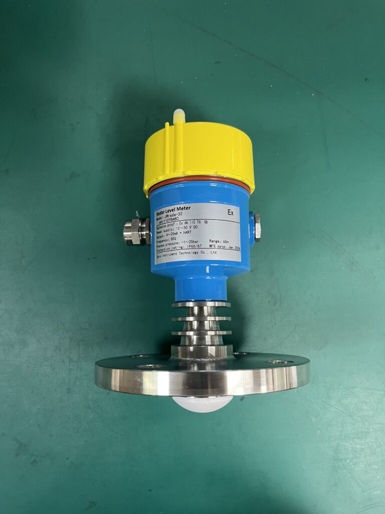
Guided wave radar (GWR) transmitters use a probe, such as a rod, cable, or coaxial structure, to guide electromagnetic pulses toward the material surface.
Although guided wave radar can perform well in many difficult applications, deposits on the probe may affect measurement reliability.
Common problems include:
- Crystallization.
- Material buildup.
- Sticky deposits.
- Coating or scaling.
- Condensation-related contamination.
- Conductive deposits or bridging.
Material buildup can alter the electromagnetic conditions around the probe and introduce impedance discontinuities.
These discontinuities may generate unwanted reflections, weaken the useful measurement signal, or interfere with echo identification.
Severe buildup may eventually cause incorrect or unstable measurements.
Recommended solutions
Inspect the probe condition.
Look for deposits, deformation, mechanical damage, or unwanted contact with surrounding structures.
Clean the probe according to manufacturer instructions.
Ensure that cleaning procedures are compatible with the probe material and process conditions.
Review the probe design.
For applications with heavy buildup, consider whether a different probe design offers improved performance.
Evaluate non-contact radar measurement.
In some applications, non-contact radar may reduce maintenance associated with probe contamination.
However, the new measurement arrangement must still be evaluated for foam, vapor, tank geometry, dielectric properties, and other operating conditions.
7. Antenna Condensation and Process Buildup
In addition to probe contamination, non-contact radar transmitters may experience problems caused by deposits on the antenna.
This is particularly relevant in applications involving:
- Condensing vapors.
- Sticky liquids.
- High-humidity environments.
- Crystallizing chemicals.
- Dusty or contaminated process atmospheres.
Condensation or buildup on the antenna can weaken, scatter, or distort the transmitted and received radar signals.
As the contamination accumulates, echo quality may deteriorate.
The transmitter may then experience intermittent signal loss or incorrect echo tracking.
Recommended solutions
Inspect the antenna surface and process connection for contamination.
Where supported by the instrument design, consider suitable antenna purging or other manufacturer-approved measures.
Verify that the transmitter installation is appropriate for the process temperature, pressure, and condensation conditions.
For recurring contamination, review whether a different antenna design or process connection would be more suitable.
8. Incorrect Damping Settings
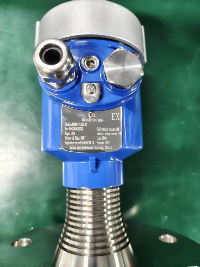
Damping is commonly used in level transmitters to smooth rapid changes in the measured signal.
When properly configured, damping can improve the stability of the displayed value and analog output.
However, damping does not eliminate the underlying cause of measurement errors.
For example, increasing the damping time may make a fluctuating trend appear smoother, but the radar transmitter may still be tracking an incorrect echo.
Excessive damping also introduces a response delay.
This becomes particularly important in applications involving:
- Rapid filling operations.
- Pump protection.
- High-level alarms.
- Low-level protection.
- Process control requiring fast response.
Recommended approach
First confirm that the transmitter is detecting the correct surface echo.
Then adjust damping according to the process response requirements.
For slowly changing storage tank levels, a longer damping time may be acceptable.
For fast-changing process vessels, shorter damping may be required.
Always consider the response time of the complete measurement and control system, including transmitter damping, PLC/DCS filtering, alarm delays, and control-loop behavior.
Safety-related measurements must be configured according to the approved process safety requirements.
9. Step-by-Step Troubleshooting Procedure
When a radar level transmitter shows frequent fluctuations, a structured troubleshooting process is more effective than changing several settings at the same time.
Step 1: Confirm whether the liquid level is actually fluctuating
Check the process operating conditions.
Review pump operation, filling rates, agitator status, and other relevant process information.
Where a safe and reliable independent level indication is available, compare the actual level with the radar reading.
Step 2: Compare transmitter and PLC/DCS readings
Determine whether the fluctuation is visible on the transmitter itself.
If both readings fluctuate similarly, focus initially on the measurement conditions and transmitter diagnostics.
If the transmitter is stable but the PLC/DCS value fluctuates, investigate the output signal, wiring, communication, analog input module, and control system configuration.
Step 3: Review transmitter diagnostics
Check for diagnostic messages relating to:
- Echo loss.
- Low signal quality.
- Measurement uncertainty.
- Sensor or electronics faults.
- Output signal faults.
- Incorrect configuration.
The available diagnostic functions depend on the transmitter model.
Step 4: Analyze the radar echo curve
Look for weak surface reflections, false echoes, or changes in echo tracking.
Determine whether the instrument consistently identifies the same surface reflection.
Step 5: Inspect installation and process conditions
Check the antenna orientation, nozzle arrangement, tank internals, foam formation, and possible buildup.
For guided wave radar, inspect the probe where safe and practical.
Step 6: Check electrical connections and signal transmission
Inspect the power supply, cable routing, shielding, grounding, and output signal.
Step 7: Adjust transmitter settings carefully
After identifying the likely cause, review the relevant settings, such as:
- False echo suppression.
- Echo tracking parameters.
- Damping time.
- Measurement range.
- Tank geometry or application configuration.
Document the original settings before making changes.
Step 8: Verify performance
Observe the transmitter under representative operating conditions.
Compare measured values with independent level information where available.
Confirm that the measurement remains stable without introducing unacceptable response delays.
10. Troubleshooting Reference Table
| Symptom | Possible Cause | Recommended Check |
|---|---|---|
| Sudden jumps in measured level | False echo tracking or echo loss | Echo curve and diagnostics |
| Fluctuations during mixing | Turbulence or agitator reflections | Process conditions and installation |
| Unstable readings in foaming liquids | Radar signal attenuation or foam reflection | Echo strength and foam conditions |
| Stable local display but unstable DCS reading | Signal transmission or control system issue | 4–20 mA loop, wiring, AI module |
| Fluctuations during VFD operation | Electrical interference | Cable routing, shielding, grounding |
| Measurement problems after long-term operation | Antenna or probe contamination | Sensor inspection |
| Smooth trend but delayed level response | Excessive damping | Damping and system response time |
| Repeated measurement loss | Weak echo or unsuitable application configuration | Echo quality, installation and diagnostics |
11. Preventive Maintenance Recommendations
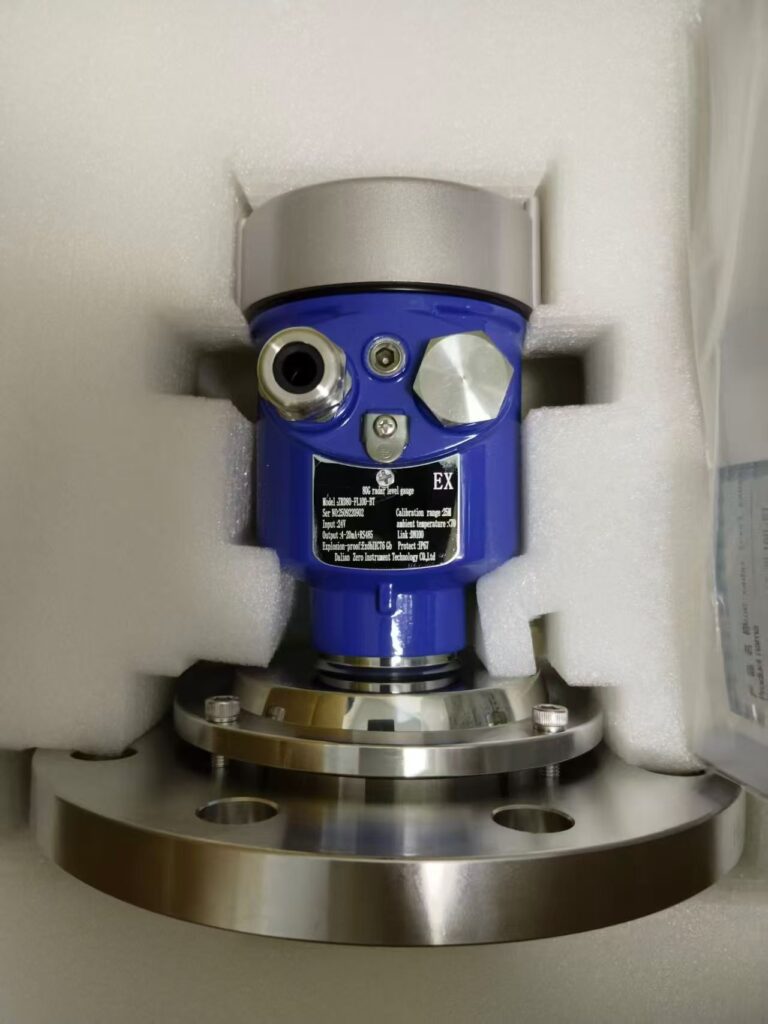
Many radar level measurement problems can be prevented through proper installation, configuration, and routine inspection.
Recommended practices include:
- Select a suitable radar frequency and antenna design for the application.
- Avoid installing transmitters directly above filling streams or major tank obstructions.
- Verify installation geometry against the manufacturer’s instructions.
- Preserve reference echo curves and commissioning settings when possible.
- Periodically review signal quality and diagnostic events.
- Inspect antennas and guided wave radar probes for contamination where required.
- Maintain proper instrument cable routing and grounding.
- Avoid unnecessary changes to false echo suppression parameters.
- Confirm damping settings are compatible with process control requirements.
- Recheck measurement performance after major process or tank modifications.
For critical applications, measurement reliability should be verified through an appropriate inspection, calibration, or proof-testing program based on the instrumentation design and plant maintenance requirements.
12. Conclusion
Unstable radar level readings are a common industrial instrumentation problem, but they do not always indicate that the transmitter itself is faulty.
The most frequent causes include liquid surface turbulence, foam interference, false reflections from tank internals, electrical noise, improper signal processing, and contamination of radar antennas or guided wave radar probes.
The key to successful troubleshooting is identifying where the instability originates.
If the transmitter itself displays unstable measurements, investigate process conditions, echo quality, installation, and sensor diagnostics.
If the local transmitter reading is stable but the PLC/DCS value fluctuates, investigate signal transmission and the control system.
Most importantly, avoid using excessive damping or aggressive false echo suppression simply to make the trend curve appear stable.
A smooth trend does not necessarily mean that the measurement is accurate.
By combining echo curve analysis, process investigation, proper electrical installation, and careful parameter configuration, instrumentation engineers can significantly improve radar level measurement reliability and reduce unnecessary maintenance.
Zero Instrument provides industrial level measurement solutions, including non-contact radar level transmitters, guided wave radar level transmitters, and other process instrumentation for demanding industrial applications.
For technical support, instrument selection, or level measurement inquiries, visit www.zeroinstrument.com.