
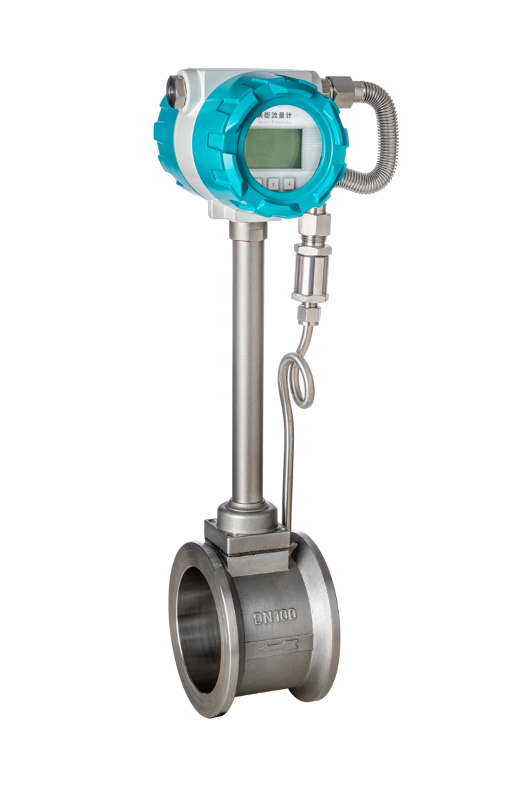
Vortex flow meters are widely used in chemical processing plants, steam distribution systems, heating networks, water treatment facilities, and other industrial applications. Their simple structure, lack of moving parts, and relatively low maintenance requirements make them a popular choice for measuring the flow of liquids, gases, and steam.
However, low maintenance does not mean maintenance-free.
In actual industrial operations, vortex flow meters may experience unstable readings, unexpected flow fluctuations, false flow indications, or measurement errors after operating normally for months or even years.
One possible cause is mechanical vibration transmitted through the piping system. Other factors, including pressure pulsation, improper installation, electrical interference, and changes in process conditions, can produce similar symptoms.
Understanding these problems and establishing an effective maintenance program can significantly improve measurement reliability.
This guide explains how vibration affects vortex flow measurement, what technicians should inspect during routine maintenance, how to reduce interference, and how to troubleshoot common measurement problems.
1. How Does Vibration Affect a Vortex Flow Meter?
1.1 Understanding the Measurement Principle
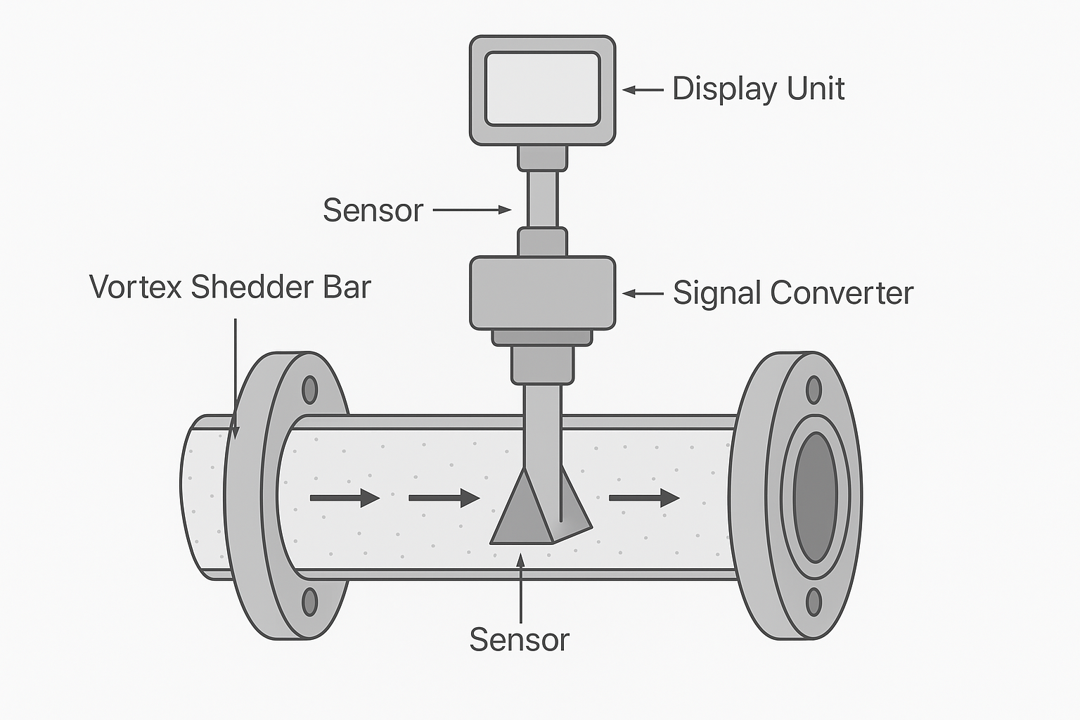
A vortex flow meter operates according to the Kármán vortex street principle.
When fluid passes around a bluff body installed inside the measuring tube, vortices are alternately shed from opposite sides of the body.
The vortex shedding frequency is proportional to the average flow velocity within the specified operating range.
The relationship can be expressed as:
f = St × V / d
Where:
- f = Vortex shedding frequency (Hz)
- St = Strouhal number
- V = Flow velocity (m/s)
- d = Characteristic width of the bluff body (m)
The meter detects these periodic vortices using a suitable sensing mechanism, which may include piezoelectric sensors or other technologies depending on the instrument design.
The electronic transmitter processes the detected frequency and converts it into flow measurement data.
Under suitable operating conditions, this principle provides reliable flow measurement without requiring moving mechanical components.
1.2 Why Mechanical Vibration Causes Measurement Problems
In industrial plants, pumps, compressors, fans, and other rotating machinery continuously generate mechanical vibration.
These vibrations can travel through connected piping and reach the flow meter body.
Depending on the sensor design and signal-processing technology, vibration may interfere with the detection of vortex shedding.
If the interference becomes sufficiently strong, the transmitter may have difficulty distinguishing the actual vortex signal from unwanted mechanical disturbances.
Some modern vortex flow meters incorporate vibration compensation, dual-sensor arrangements, and digital signal processing to improve resistance to mechanical interference.
Nevertheless, every instrument has practical operating limits.
Excessive vibration may cause:
- Unstable instantaneous flow readings
- Unexpected fluctuations in DCS or PLC trends
- False flow indications under verified zero-flow conditions
- Incorrect accumulated flow totals
- Reduced measurement repeatability
- Increased mechanical stress on sensor components and electrical connections
Important: Flow fluctuations do not automatically indicate vibration interference. Pressure pulsation, two-phase flow, electrical noise, and process instability must also be considered.
1.3 Why Problems May Develop After Long-Term Operation
A vortex flow meter may operate normally immediately after installation but develop measurement problems later.
Possible causes include:
- Loosened pipe supports or brackets
- Worn pump bearings
- Changes in rotating equipment vibration
- Piping stress caused by thermal expansion
- Deterioration of flexible connectors
- Loose electrical terminals
- Changes in operating flow rates or process conditions
This is why vibration inspection should be included in routine preventive maintenance rather than performed only during commissioning.
2. Daily Vortex Flow Meter Maintenance Checklist
Routine inspection should focus on identifying potential problems before they affect measurement accuracy.
2.1 Inspect the Meter Body and Connected Piping
Check the flow meter and nearby piping for abnormal movement, looseness, or visible mechanical damage.
Pay particular attention to installations near:
- Centrifugal pumps
- Reciprocating compressors
- Large fans
- Control valves
- Other equipment that generates mechanical vibration or pressure pulsation
During inspection, examine pipe supports, brackets, anchor points, and vibration isolation components.
Look for loose fasteners, cracked welds, excessive movement, or deteriorated support materials.
Where abnormal vibration is suspected, use an appropriate vibration measurement instrument rather than relying solely on visual or physical observation.
Maintenance recommendation: Record vibration measurements and compare them with previous readings and applicable equipment limits.
Do not touch hot, hazardous, moving, or otherwise unsafe equipment during inspection.
2.2 Check Flanges and Mechanical Connections
Continuous vibration may contribute to loosening mechanical connections or increasing mechanical stress on the meter body.
Inspect the flanges for:
- Process leakage
- Loose or missing bolts
- Damaged gaskets
- Corrosion
- Misalignment
- Evidence of excessive piping stress
If corrective work is necessary, follow approved plant isolation and maintenance procedures.
Flange bolts should be tightened according to the manufacturer’s specified torque and tightening sequence.
Avoid uneven tightening that could create additional mechanical stress.
Safety reminder: Never loosen or tighten pressure-containing connections without following the appropriate site-approved procedure.
2.3 Inspect Electrical Connections and Grounding
Mechanical vibration can also affect electrical wiring.
Repeated movement may loosen terminals, damage cable insulation, or place excessive tension on cable connections.
Check that:
- Electrical terminals are properly secured
- Cable glands are correctly installed
- Cable insulation is undamaged
- Electrical enclosures remain sealed
- Cables have adequate strain relief
- Grounding and shielding comply with the manufacturer’s instructions
Cable shielding arrangements depend on the instrument design and installation requirements.
A single-point shield connection may be appropriate for some systems, while other installations require different arrangements.
Always follow the manufacturer’s wiring diagram and applicable electrical installation requirements.
For hazardous-area instruments, electrical inspection must also comply with the relevant explosion-protection and site safety procedures.
2.4 Check the Transmitter Signal and Flow Trends
Do not evaluate a vortex flow meter only by confirming that its display is operating.
Review the measurement signal and historical flow data.
Useful checks include:
- Instantaneous flow stability
- Totalized flow values
- Pulse output behavior
- Diagnostic messages
- Sensor signal quality, where available
- Changes in readings at different operating loads
If the process is confirmed to be at zero flow, check whether the transmitter continues to indicate flow.
Unexpected readings under verified zero-flow conditions may suggest vibration interference, electrical noise, or unsuitable parameter settings.
Compare flow trends with pump speed, valve movement, pressure fluctuations, and other relevant process variables.
This helps distinguish mechanical interference from actual changes in process flow.
2.5 Inspect Process Conditions and the Bluff Body
Although vortex flow meters have no moving internal measuring components, the bluff body can still accumulate deposits.
Common problems include:
- Scale formation
- Sediment accumulation
- Corrosion
- Erosion
- Process material buildup
These conditions may change vortex formation and affect the meter’s measurement performance.
Also consider whether the fluid contains gas bubbles, liquid droplets, or other phases that may interfere with stable vortex shedding.
For steam applications, check for condensate accumulation and unsuitable drainage arrangements.
For liquid applications, verify that the meter remains completely filled during operation.
For gas applications, evaluate whether operating pressure, temperature, and flow velocity remain within the manufacturer’s specified range.
3. Practical Methods to Reduce Vibration Interference
3.1 Maintain Proper Pipe Supports
Adequate piping support is one of the most important measures for reducing excessive mechanical movement.
Inspect supports for looseness, corrosion, structural damage, and deterioration.
The location and type of pipe supports should be determined according to the instrument manufacturer’s recommendations and the piping system design.
There is no universal requirement that every vortex flow meter must have fixed supports exactly 2D upstream and downstream.
Support arrangements must also consider:
- Pipe diameter and weight
- Operating temperature
- Thermal expansion
- Mechanical loads
- Pipe stress
- Vibration characteristics
Where vibration isolation materials are appropriate, their selection must consider mechanical loading, environmental conditions, and long-term durability.
Do not install rubber pads or other flexible materials indiscriminately, as inappropriate supports can create additional vibration or piping stress problems.
3.2 Inspect Flexible Connectors and Expansion Joints
Flexible connectors may help reduce the transmission of certain mechanical vibrations.
They are frequently used in piping systems connected to rotating equipment.
During routine maintenance, inspect flexible connectors for:
- Cracking
- Bulging
- Aging
- Leakage
- Excessive deformation
- Damaged reinforcement components
Ensure that the connectors are suitable for the operating pressure, temperature, fluid, and expected mechanical movement.
The piping system must also have an appropriate method of managing pressure thrust and mechanical loads.
Important: Flexible connectors do not necessarily eliminate fluid pressure pulsation.
If the source of interference is hydraulic or pneumatic pulsation, additional process-side measures may be required.
3.3 Optimize Transmitter Filtering Parameters
Many vortex flow meter transmitters allow technicians to configure damping or signal filtering parameters.
Increasing the damping time can reduce visible fluctuations in the displayed or transmitted flow signal.
However, excessive damping may delay the response to actual flow changes.
Before changing parameters:
- Record the original settings.
- Review the manufacturer’s configuration instructions.
- Confirm the actual process conditions.
- Adjust the settings within the permitted range.
- Check the measurement response under normal operating conditions.
Filtering should be considered a signal-processing adjustment, not a substitute for correcting mechanical vibration.
3.4 Set Low-Flow Cutoff Carefully
Low-flow cutoff is another common transmitter function.
Its purpose is to suppress small flow indications below a configured threshold.
This can help prevent unwanted totalization caused by certain noise conditions.
However, setting the cutoff too high can cause actual low-flow conditions to be ignored.
For example, if the cutoff threshold is set above the lowest legitimate operating flow, the meter may report zero even when fluid is moving through the pipe.
Therefore, low-flow cutoff must be configured with reference to the instrument’s specified measuring range and the actual process requirements.
Never use an excessively high low-flow cutoff simply to hide unstable readings.
3.5 Clean the Bluff Body When Necessary
Deposits on the bluff body can change the fluid flow pattern and affect measurement performance.
Where process conditions require internal inspection, follow an approved shutdown and isolation procedure.
Before opening the measuring section:
- Isolate the meter from the process
- Confirm that pressure has been relieved
- Allow the equipment to cool where necessary
- Drain or purge hazardous process fluid safely
- Follow the manufacturer’s maintenance instructions
Clean the bluff body using suitable materials and methods.
Avoid abrasive tools that may damage its surface or alter its geometry.
After reassembly, verify the installation condition, sealing integrity, and measurement operation.
3.6 Distinguish Mechanical Vibration from Pressure Pulsation
Mechanical vibration and fluid pressure pulsation can produce similar measurement symptoms, but they require different corrective measures.
Mechanical vibration
Possible sources include damaged pump bearings, loose pipe supports, structural resonance, or rotating machinery imbalance.
Corrective measures may include repairing rotating equipment, improving pipe support, or modifying vibration transmission paths.
Pressure pulsation
Possible sources include reciprocating pumps, compressors, rapidly changing valve positions, and unstable process conditions.
Corrective measures may include reviewing equipment operation, improving piping arrangements, or installing a properly engineered pulsation dampening system.
Additional straight pipe alone may not eliminate pressure pulsation.
Correctly identifying the source is essential before modifying the installation.
4. Installation Factors That Affect Vortex Flow Meter Accuracy
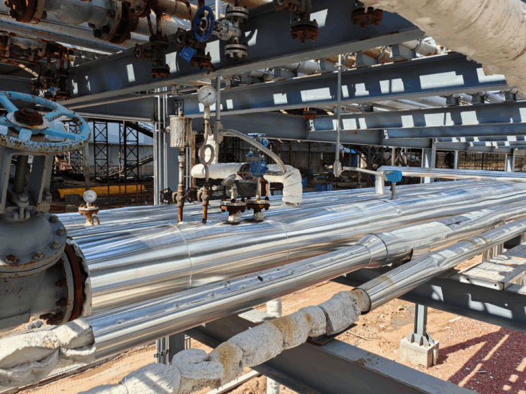
Vibration control is only one part of reliable vortex flow measurement.
Installation conditions can also influence measurement accuracy and stability.
4.1 Provide Adequate Straight Pipe Lengths
Vortex flow meters generally require suitable upstream and downstream straight pipe sections.
Elbows, valves, reducers, and other disturbances can change the flow velocity profile.
The required straight pipe lengths depend on the meter design and the upstream piping configuration.
Follow the manufacturer’s installation instructions rather than applying a single straight-pipe requirement to all vortex meters.
4.2 Avoid Unstable Flow Conditions
Where practical, select installation locations away from severe flow disturbances.
Particular attention should be given to:
- Pump discharge piping
- Reciprocating equipment
- Control valves
- Partially closed valves
- Multiple closely spaced elbows
If the available installation space is limited, discuss the piping arrangement with the flow meter manufacturer before installation.
4.3 Prevent Two-Phase Flow Problems
Vortex flow meters are generally intended for appropriate single-phase operating conditions unless the specific instrument and application support otherwise.
Gas bubbles in liquid service or liquid droplets in gas service may produce unstable measurement signals.
For steam service, condensate management and correct piping arrangements are especially important.
4.4 Check the Operating Flow Range
Every vortex flow meter has a specified minimum and maximum operating range.
At very low flow velocities, stable vortex shedding may not be sufficient for reliable measurement.
At excessive velocities, other limitations such as pressure loss, mechanical loading, or instrument operating limits may become relevant.
Confirm that the expected flow conditions remain within the meter’s approved range.
5. Vortex Flow Meter Troubleshooting Guide
The following table summarizes common measurement problems and practical diagnostic actions.
| Problem | Possible Causes | Recommended Checks |
|---|---|---|
| Flow fluctuates continuously | Mechanical vibration, pressure pulsation, unstable process flow | Compare vibration, flow, and pressure trends |
| Flow indicated when actual flow is zero | Vibration interference, electrical noise, configuration | Verify zero flow and inspect sensor signals |
| Flow reads lower than expected | Deposits, incorrect range, installation problems | Inspect bluff body and operating conditions |
| Flow disappears at low rates | Flow below measuring limit, excessive low-flow cutoff | Check minimum flow and configuration |
| Intermittent signal loss | Loose wiring, power supply problems, sensor faults | Inspect terminals, diagnostics, and power |
| Measurement changes with pump operation | Vibration, pulsation, genuine process flow changes | Compare pump condition and process data |
Practical Troubleshooting Example
Consider a vortex flow meter installed in an industrial steam distribution system.
The meter has operated normally for an extended period but begins producing unstable instantaneous flow readings.
The fluctuations appear more frequently when nearby rotating equipment operates.
A structured investigation could proceed as follows:
Step 1: Verify the process conditions.
Check whether steam demand, pressure, and temperature have changed.
Step 2: Review measurement trends.
Compare flow fluctuations with the operating condition of nearby machinery.
Step 3: Inspect the piping system.
Look for loose supports, abnormal movement, and signs of excessive vibration.
Step 4: Check electrical connections.
Verify cable integrity, terminal security, and transmitter diagnostic information.
Step 5: Perform corrective maintenance.
Where a loose or damaged support is identified, repair it according to the piping design and applicable safety procedures.
Step 6: Verify measurement performance.
After maintenance, compare the instrument’s measurement trends under similar process conditions.
If unstable readings remain, continue investigating pressure pulsation, process conditions, sensor performance, and calibration.
This example illustrates a diagnostic procedure rather than a documented customer installation.
6. Preventive Maintenance and Calibration
A preventive maintenance program should be based on operating conditions, instrument criticality, and the manufacturer’s recommendations.
Routine Inspection
Inspect the flow meter display, diagnostics, piping condition, and available process trends.
Look for changes in vibration, flow stability, or electrical connection condition.
Periodic Maintenance
At planned intervals, inspect mechanical supports, cable connections, seals, and vibration isolation components.
Record any unusual findings and corrective work performed.
Scheduled Shutdown Inspection
Where necessary and permitted by the maintenance plan, inspect the bluff body for deposits, erosion, corrosion, or mechanical damage.
Check the instrument for installation stress and verify its condition before returning it to service.
Calibration and Verification
Calibration or performance verification should be performed according to the applicable maintenance plan, manufacturer’s guidance, and any relevant regulatory or contractual requirements.
Critical measurement points or instruments exposed to severe conditions may require more frequent verification.
It is important to understand that calibration alone cannot correct mechanical vibration or unsuitable installation conditions.
A properly calibrated meter may still produce unstable readings when operating in an unsuitable environment.
7. Recommended Maintenance Checklist
The following intervals are illustrative starting points for a maintenance program. Actual schedules should be adapted to site conditions, risk assessments, and manufacturer instructions.
| Maintenance Item | Inspection Requirements | Example Interval |
|---|---|---|
| Piping vibration and supports | Abnormal movement, looseness, structural condition | Monthly |
| Flanges and mechanical connections | Leakage, corrosion, mechanical damage | Monthly |
| Electrical connections | Terminal security, cable condition, grounding | Monthly |
| Transmitter parameters | Filtering, cutoff, diagnostics, signal behavior | Quarterly |
| Bluff body | Deposits, wear, corrosion, damage | During planned shutdown |
| Flexible connectors | Cracking, deformation, deterioration | Every 6 months |
| Measurement verification | Accuracy and performance checks | Risk-based schedule |
Maintenance records should include the inspection date, operating conditions, observed defects, corrective measures, and verification results.
These records can help identify recurring problems and support preventive maintenance planning.
8. Common Maintenance Mistakes to Avoid
Mistake 1: Assuming a Displayed Flow Value Must Be Correct
A functioning display does not guarantee measurement accuracy.
The transmitter may continue to display flow even when interference affects the measured signal.
Always evaluate measurement behavior together with process conditions.
Mistake 2: Relying Entirely on Flexible Connectors
Flexible connectors may reduce some types of mechanical vibration, but they cannot address every source of measurement instability.
Piping resonance, pressure pulsation, and process-related disturbances may require other solutions.
Mistake 3: Increasing Low-Flow Cutoff Excessively
An excessive cutoff setting may suppress unwanted indications but also prevent legitimate low flow from being measured.
Mistake 4: Ignoring Installation Conditions
Replacing a meter without correcting poor piping support or unsuitable process conditions may not solve the original problem.
Mistake 5: Selecting a Standard Meter for Severe Vibration Applications
For applications involving significant vibration, consider vortex flow meters with suitable vibration resistance or compensation features.
The instrument should be evaluated against the expected operating conditions and the manufacturer’s published specifications.
9. Frequently Asked Questions
Why does my vortex flow meter show flow when the pipeline is not flowing?
Possible causes include mechanical vibration, electrical interference, or configuration problems.
First confirm that the process is genuinely at zero flow, then inspect the meter’s diagnostic information, electrical connections, and vibration conditions.
Can pipe vibration damage a vortex flow meter?
Severe or prolonged vibration may contribute to mechanical fatigue, loosen electrical connections, or affect sensitive instrument components.
The actual risk depends on vibration severity, frequency, meter construction, and installation conditions.
Can adjusting damping eliminate vibration interference?
No. Damping can smooth the reported signal, but it does not eliminate the source of mechanical vibration.
Excessive damping may also slow the response to real flow changes.
Why is my vortex flow meter unstable at low flow?
The actual flow may be near or below the meter’s specified lower measuring limit.
Vibration, electrical noise, or an unsuitable low-flow cutoff setting may also contribute.
How often should a vortex flow meter be calibrated?
There is no universal calibration interval suitable for every application.
The interval should be determined according to the manufacturer’s recommendations, process criticality, operating history, and applicable requirements.
Are vortex flow meters suitable for steam measurement?
Yes. Vortex flow meters are commonly used in appropriate steam measurement applications.
However, correct sizing, pressure and temperature compensation where required, condensate management, and suitable installation conditions are essential.
Conclusion
Vortex flow meters offer reliable flow measurement with relatively low mechanical maintenance requirements, but their performance depends on more than the instrument itself.
Pipe vibration, pressure pulsation, installation conditions, electrical connections, and process characteristics can all influence measurement stability.
The most effective maintenance strategy combines regular inspection, proper piping support, careful transmitter configuration, preventive maintenance, and systematic troubleshooting.
Instead of immediately replacing an instrument when flow readings become unstable, technicians should investigate the surrounding process and installation conditions.
By identifying problems early and applying appropriate corrective measures, industrial facilities can reduce unnecessary downtime, improve measurement reliability, and extend instrument service life.
At Zero Instrument, we believe reliable flow measurement begins with correct instrument selection, proper installation, and consistent maintenance.