
Industrial instruments are becoming increasingly intelligent and precise. Modern flowmeters, pressure transmitters, radar level transmitters, analyzers, PLCs, and DCS I/O modules often contain sensitive electronic circuits that can be damaged by transient overvoltages.
A surge may last only microseconds, but its voltage can rise far above the normal operating level. A single severe surge can destroy an electronic board instantly, while repeated smaller surges may gradually degrade components and shorten instrument life.
This is where a Surge Protection Device (SPD) becomes important.
But how does an SPD actually work? What is the difference between MOV, GDT, and TVS protection? And how should you select an SPD for 24 VDC power, 4–20 mA, HART, or RS485 instrument circuits?
This guide explains the fundamentals from an industrial instrumentation perspective.
1. What Is a Surge?
A surge, also called a transient overvoltage, is a short-duration voltage or current spike that exceeds the normal operating level of an electrical circuit.
Common sources include:
- Direct or nearby lightning strikes
- Lightning-induced electromagnetic fields
- Switching of motors, transformers, and contactors
- Switching of large inductive loads
- Power grid disturbances
- Ground potential differences
- Long outdoor power and signal cables
Industrial instrumentation is particularly vulnerable because field devices are often connected to long cables running between outdoor equipment, junction boxes, control cabinets, PLCs, and DCS systems.
These cables can effectively act as paths for surge energy.
2. How Can Surges Damage Industrial Instruments?
Surge damage generally occurs in two ways.
Immediate Damage
A high-energy surge may exceed the insulation or semiconductor withstand capability of the instrument.
Typical consequences include:
- Burned PCB components
- Damaged power supply modules
- Failed communication interfaces
- Burned analog input cards
- Complete transmitter failure
For example, a surge entering through a 4–20 mA cable may damage not only the field transmitter but also the PLC or DCS analog input channel connected to it.
Progressive Degradation
Not every surge causes an immediate failure.
Repeated lower-energy transients can gradually weaken electronic components.
Possible symptoms include:
- Measurement drift
- Unstable output
- Intermittent communication failures
- Unexpected instrument resets
- Reduced service life
This type of damage is often more difficult to diagnose because the instrument may continue operating for some time before eventually failing.

3. How Does an SPD Work?
The basic principle is simple:
Under normal operating conditions, the SPD has little or no influence on the circuit. When the voltage exceeds a defined level, the SPD rapidly conducts the surge current away from the protected equipment and limits the voltage reaching the instrument.
You can think of an SPD as an emergency bypass for excessive electrical energy.
Under normal conditions:
Power/Signal → Instrument
During a surge:
Surge → SPD → PE/Earth
while the voltage reaching the instrument is limited to a safer level.
Once the transient event disappears, the SPD returns to its normal high-impedance state.
4. MOV vs GDT vs TVS: What Is the Difference?
Three common protection technologies are widely used in surge protection circuits.
| Component | Main Characteristic | Surge Capability | Typical Instrumentation Application |
|---|---|---|---|
| MOV – Metal Oxide Varistor | Fast voltage clamping | Medium to high | AC/DC power protection, control cabinets |
| GDT – Gas Discharge Tube | Very high surge current capability | Very high | Outdoor junction boxes, primary protection |
| TVS – Transient Voltage Suppression Diode | Extremely fast clamping | Relatively low | 4–20 mA, RS485 and sensitive electronics |
Each technology has advantages and limitations.
MOV
MOVs are widely used in power supply SPDs because they can absorb relatively large amounts of surge energy while responding quickly.
They are commonly found in:
- Distribution cabinets
- Instrument control cabinets
- AC power protection
- DC power protection
However, MOVs gradually degrade after repeated surge events and may eventually require replacement.
GDT
A gas discharge tube can handle very high surge currents.
It is therefore commonly used as a first-stage protection element, particularly where lightning-induced surges are possible.
Typical locations include:
- Outdoor junction boxes
- Long field cable entrances
- Building entry points
- High-exposure industrial installations
Its disadvantage is that it generally does not provide the same fine voltage clamping as semiconductor devices.
TVS Diode
TVS diodes respond extremely quickly and provide precise voltage clamping.
They are particularly useful for protecting sensitive electronic and communication circuits such as:
- 4–20 mA
- RS485
- Digital I/O
- Low-voltage sensor circuits
In practical SPDs, manufacturers may combine several technologies to achieve both high surge-current capability and low residual voltage.
5. Type 1, Type 2, and Type 3 SPD Protection
Modern SPD systems are generally designed using coordinated protection stages.
Type 1 SPD — Primary Protection
Type 1 SPDs are installed near the main incoming power supply where significant lightning current may enter the electrical system.
Their primary purpose is to handle high-energy surge currents.
Typical location:
Main distribution board
Type 2 SPD — Secondary Protection
Type 2 SPDs are commonly installed in downstream distribution panels and industrial control cabinets.
They reduce the residual surge voltage that passes through the first protection stage.
Typical locations:
- Control room distribution panel
- MCC
- Instrument cabinet
- PLC/DCS cabinet
Type 3 SPD — Equipment-Level Protection
Type 3 protection is installed close to sensitive equipment and provides fine protection against remaining transient voltage.
Typical applications include:
- Precision instruments
- PLC/DCS equipment
- Analyzers
- Electronic controllers
A coordinated system therefore looks approximately like this:
Incoming Power → Type 1 SPD → Type 2 SPD → Type 3 Protection → Sensitive Equipment
Using several coordinated protection stages is generally more effective than relying on one SPD alone.

6. Key Parameters When Selecting an SPD
Choosing an SPD based only on its maximum surge current is not enough.
Several parameters should be considered.
Uc — Maximum Continuous Operating Voltage
Uc is the maximum voltage that can be continuously applied to the SPD without causing it to operate abnormally.
The SPD’s Uc must be suitable for the normal operating voltage of the circuit.
For example, an SPD intended for a 24 VDC instrumentation circuit should be selected specifically for that voltage range rather than using an SPD designed for mains AC circuits.
Up — Voltage Protection Level
Up indicates the residual voltage that may appear across the SPD during a surge event.
For sensitive electronic equipment, a lower Up generally provides better protection, provided it is compatible with the normal operating voltage.
In — Nominal Discharge Current
In indicates the surge current the SPD can repeatedly withstand under specified test conditions.
It is an important parameter when evaluating the expected surge exposure.
Imax — Maximum Discharge Current
Imax represents the maximum surge current a Type 2 SPD can handle under specified conditions.
A larger number does not automatically mean the SPD is more suitable. Coordination with the protected equipment and upstream protection remains important.
Iimp — Impulse Current
Iimp is particularly relevant to Type 1 SPDs and represents their capability to handle high-energy lightning current impulses.
7. Surge Protection for 24 VDC Industrial Instruments
Many modern field instruments operate from 24 VDC, including:
- Electromagnetic flowmeters
- Pressure transmitters
- Radar level transmitters
- Ultrasonic level transmitters
- Temperature transmitters
- Gas analyzers
- PLC/DCS field devices
A common architecture is:
AC Supply → AC SPD → 24 VDC Power Supply → DC SPD → Field Instrument
Protection should be coordinated according to the installation environment.
For instruments installed outdoors or connected through long cables, protecting only the AC input of the power supply may not be sufficient.
Surges can also enter through the DC field wiring.
8. Surge Protection for 4–20 mA Signals
A 4–20 mA current loop may appear simple, but the analog input electronics connected to the loop can be highly sensitive to transient voltage.
A typical protected loop is:
Field Transmitter → Signal SPD → PLC/DCS Analog Input
For long outdoor cable runs or lightning-exposed installations, protection may be required at both ends:
Transmitter → SPD → Long Cable → SPD → PLC/DCS
When selecting a 4–20 mA signal SPD, consider:
- Nominal operating voltage
- Maximum continuous voltage
- Loop resistance
- Voltage drop
- Surge current capability
- Protection level
- Grounding arrangement
Excessive SPD resistance or voltage drop can affect the available loop voltage, particularly in systems with long cable runs or multiple loop-powered devices.

9. Special Considerations for HART Signals
HART communication superimposes a digital signal onto the conventional 4–20 mA current loop.
Therefore, an SPD used in a HART circuit must not significantly attenuate the HART communication signal.
The selected SPD should be explicitly suitable for:
4–20 mA + HART communication
Using an inappropriate protection device may allow the analog current signal to operate normally while causing unstable or failed HART communication.
10. Surge Protection for RS485 Networks
RS485 is widely used in industrial instrumentation for Modbus RTU and other serial communication systems.
However, long RS485 cables can be particularly exposed to induced surges and ground potential differences.
A typical architecture is:
Instrument → RS485 SPD → Communication Cable → RS485 SPD → PLC/Gateway
When selecting an RS485 SPD, check:
- Signal operating voltage
- Maximum data rate
- Bandwidth
- Capacitance
- Insertion loss
- Surge current capability
- Grounding method
Do not simply install a general-purpose power SPD on an RS485 signal line.
The protection device must be designed for data communication.
11. Grounding Is Critical
Even a high-quality SPD may provide poor protection if it is installed incorrectly.
The surge current needs a low-impedance path to earth.
Three general principles are particularly important:
Keep Ground Connections Short
Long grounding conductors increase inductance.
During a fast surge event, even a relatively small conductor inductance can generate significant additional voltage.
Therefore:
Keep SPD grounding conductors as short and straight as practicable.
Avoid unnecessary loops and bends.
Use an Appropriate Conductor Size
Grounding conductor size should comply with the SPD manufacturer’s instructions and applicable electrical standards.
High-energy power SPDs generally require larger conductors than signal-line SPDs.
Maintain Proper Equipotential Bonding
Poor bonding between instrument earth, cabinet earth, structural earth, and other grounding systems can create dangerous potential differences during lightning events.
A properly designed equipotential bonding system is therefore an important part of surge protection.
12. Five Common SPD Installation Mistakes
Mistake 1: Protecting Only the Power Supply
An instrument may receive surge energy through its signal cable even when its power supply is protected.
For outdoor transmitters, evaluate both:
Power lines + Signal/Communication lines
Mistake 2: Using Long Ground Wires
A long PE connection can significantly increase the residual voltage reaching the protected equipment.
Install the SPD as close as practical to the protected circuit and keep connections short.
Mistake 3: Using the Wrong SPD Voltage
If the SPD operating voltage is too low, it may conduct during normal operation.
If it is too high, the protected equipment may experience excessive voltage before the SPD begins limiting the surge.
Mistake 4: Ignoring Communication Compatibility
An inappropriate SPD can interfere with:
- HART
- RS485
- Modbus RTU
- High-speed digital signals
Always verify communication compatibility.
Mistake 5: Assuming One SPD Protects the Entire System
Surge protection works best as a coordinated system.
A single SPD installed in the main distribution board may not sufficiently protect sensitive field instrumentation hundreds of meters away.
13. Example: Protecting an Outdoor 4–20 mA Pressure Transmitter
Consider an outdoor pressure transmitter installed on a storage tank approximately 200 meters from the control room.
The transmitter uses:
- 24 VDC loop power
- 4–20 mA output
- HART communication
Because the field cable is long and installed outdoors, it may be exposed to lightning-induced transients.
A practical protection concept is:
Pressure Transmitter
↓
4–20 mA/HART Signal SPD
↓
Long Field Cable
↓
Control Cabinet Signal SPD
↓
DCS Analog Input
The control cabinet’s power supply should also have appropriate upstream surge protection.
This approach helps protect both sides of the loop rather than protecting only the field transmitter.
14. Quick SPD Selection Checklist
Before selecting an SPD for an industrial instrumentation system, check:
Are multiple protection stages required?
What is the normal operating voltage?
Is the circuit AC or DC?
Is it a power line or signal line?
Is the signal 4–20 mA, HART, RS485, or another protocol?
Is the cable installed outdoors?
How long is the cable?
Is the site exposed to lightning?
What are the SPD’s Uc and Up values?
What are its In, Imax, or Iimp ratings?
Will the SPD affect loop resistance or communication?
Is the grounding/bonding system adequate?
Can the SPD be installed with short connection conductors?
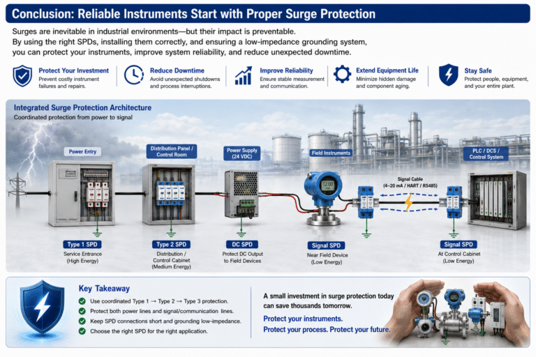
Conclusion
Surge protection for industrial instrumentation is not simply a matter of installing the SPD with the largest kA rating.
Effective protection requires coordination between:
Power protection + Signal protection + Grounding + Equipotential bonding + Correct installation
MOVs, GDTs, and TVS diodes each have different characteristics, and modern SPDs often combine these technologies to provide coordinated protection.
For industrial systems using 24 VDC, 4–20 mA, HART, RS485, PLC/DCS I/O, flowmeters, pressure transmitters, and level transmitters, particular attention should be paid to signal-line protection as well as power protection.
Most importantly, remember:
An SPD can only divert surge energy effectively when it has a properly designed, low-impedance path to earth.
Correct SPD selection and installation can prevent expensive instrument failures, reduce unexpected shutdowns, and significantly improve the reliability of industrial measurement and control systems.