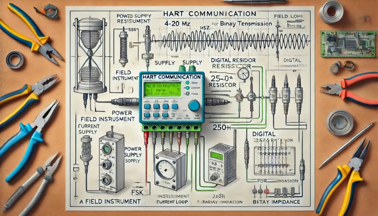
1) Why 4–20 mA still wins
In noisy industrial environments, analog current loops are resilient: the signal is immune to long-run voltage drop, easy to scale, and simple to diagnose with a meter. A single loop can carry both measurement and health information (e.g., out-of-range currents to flag faults), which is exactly why 4–20 mA remains the default in process plants.

2) What a 4–20 mA loop looks like
A basic loop consists of:
24 V DC supply powering the loop,
A transmitter that drives 4–20 mA proportional to the process variable (PV),
An indicator or controller (PLC/DCS AI) that converts loop current back to PV, often via an internal or external 250 Ω shunt to read 1–5 V by Ohm’s law.
Quick math:
4 mA →
4mA×250Ω=1.0V
20 mA →
20mA×250Ω=5.0V
Tip: If your AI already has an internal 250 Ω, don’t add another external shunt.

3) Key conversions & checks you’ll use in the field
Linear scaling (PV from loop current):
PV=PVL+16I−4(PVH−PVL)
Loop load / compliance sanity check:
Rtotal≤ImaxVsupply−Vheadroom
Use the transmitter datasheet for minimum headroom (compliance voltage). If Rtotal (wiring + shunts + AI input) is too high, you’ll never reach 20 mA.
1–5 V readout via 250 Ω:
U=I×R=(4 to 20)mA×250Ω=1 to 5V
Health ranges suggestion (NAMUR-style):
I≤3.8 mA⇒Underrange/Fault,I≥20.5 mA⇒Overrange/Fault
4) The troubleshooting playbook
Step A — Verify the loop current first
Put a DMM in series (loop mode) or use a mA clamp to read the actual current.
You’re looking for:
0 mA → open circuit / polarity reversed / blown AI fuse
≈4–20 mA steady → loop likely OK (check scaling next)
Erratic reading → noise, shielding, or grounding issues (see Step D)
Step B — Do a substitution test at the transmitter tap
Disconnect the transmitter and connect a loop calibrator / process meter at the same terminals. Source 4 → 12 → 20 mA and watch the controller.
If it tracks correctly, wiring + supply + AI are fine → issue lies in transmitter/sensor.
If it still fails, check the AI input fuse and 250 Ω presence/location.
Step C — Prove the power supply
Measure the loop supply voltage: typically 24 VDC. If in doubt, temporarily power the loop from the calibrator’s 24 V at the same point. If behavior improves, the plant supply is defective or overloaded.
Step D — Hunt noise, shielding, and grounding issues
Usual suspects: broken shields, ground loops, routing near power, marginal supply.
Use DMM (AC function) or a handheld scope to see if AC rides on the signal; a healthy loop should show only mV-level ripple.
Fix by single-end shield grounding, twisted pairs, separation from high-energy cables, or adding isolators where needed.

5) Quick diagnostic table (HTML, copy-safe)
| Symptom | Likely Cause | Quick Checks | Fix |
|---|---|---|---|
| 0 mA, controller shows nothing | Open circuit, reversed polarity, blown AI fuse | Series DMM reading; inspect terminals & AI fuse | Restore wiring, correct polarity, replace fuse |
| Loop current OK but value wrong | Scaling or 250 Ω mismatch | Confirm only one 250 Ω shunt; verify range mapping | Keep one shunt; correct AI scaling |
| 4/12/20 mA substitution test OK, but process not | Faulty transmitter/sensor or mis-ranged | Substitute at transmitter tap; compare PV | Re-range or replace transmitter/sensor |
| Intermittent/jittery PV | Noise, shield/ground issue, cable routing | DMM AC / scope; check shield land and routing | Single-point shield, twisted pair, reroute, add isolator |
| Hits top but won’t reach 20 mA | Insufficient compliance voltage (loop load too high) | Compute \(R_{\text{total}}\); measure supply under load | Reduce resistance, raise supply, or change AI input |
6) Good wiring patterns to standardize
Two-wire (loop-powered) transmitters: +24 V → transmitter “+”; transmitter “–” → AI “+”; AI “–” back to supply “–”.
Three-/four-wire (self-powered): Check whether AI is passive (sinking) or active (sourcing); never drive an active AI from an active transmitter without proper interfacing.
Keep one—and only one—250 Ω shunt in the measurement path.
7) Commissioning & safety notes
De-energize before moving meter leads; many loop failures happen while “just checking something”.
Label shield landing points; enforce single-end grounding policy.
For hazardous areas, place barriers/isolators correctly in the loop (per intrinsically safe design files).
8) Handy pocket formulas
1–5 V conversion: U=I×R=(4 to 20)mA×250Ω=1 to 5V
PV from current: PV=PVL+16I−4(PVH−PVL)
Total loop resistance limit: Rtotal≤ImaxVsupply−Vheadroom

Wrap-up
Start with the current reading, prove the wiring/AI with a substitution test, isolate the power supply, and then clean up noise. This disciplined flow solves the majority of loop problems in minutes—and it’s simple enough to apply under pressure on a live plant.
