1. Introduction
Pressure transmitters are widely used in boilers, steam systems, compressors, and chemical processes. However, due to harsh environments, installation mistakes, and signal interference, various failures frequently occur.
This document summarizes 11 real-world cases of common pressure transmitter malfunctions, including their symptoms, root causes, and corrective actions.
2. Case Studies of Common Failures
Case 1 — Furnace Negative Pressure Signal Lost
Phenomenon: Boiler furnace negative pressure suddenly disappeared.
Cause: Sampling rubber tube of the micro-pressure transmitter ruptured and disconnected, causing the positive port to open to atmosphere.
Quick Fix: Replace sampling tube. Switch combustion control to manual mode before intervention.
Case 2 — Newly Installed Transmitter No Display
Phenomenon: New transmitter showed no output.
Cause: Signal isolator damaged due to wiring replacement without power shutdown (24V positive grounded).
Quick Fix: Replace signal isolator. Ensure power is disconnected before rewiring.
Case 3 — Pressure Signal Fluctuates with VFD Operation
Phenomenon: Transmitter output fluctuated when variable frequency drive (VFD) was running.
Cause: Motor had no grounding wire, causing strong EMI interference.
Quick Fix: Add proper grounding to motor.
Case 4 — Steam Pressure Signal Fluctuation
Phenomenon: Transmitter and control room indicator fluctuated simultaneously.
Cause: High resistance (~200 Ω) on signal cable shield grounding.
Quick Fix: Re-ground the shield properly.
Case 5 — Zero Drift of Newly Installed Micro-Pressure Transmitter
Phenomenon: Output current not equal to 4 mA at 0 Pa.
Cause: Sensitive element weight affecting zero point after installation.
Quick Fix: Readjust zero point after mounting. Install sensor with diaphragm axis perpendicular to gravity.
Case 6 — Steam Pressure Indication Too Low
Phenomenon: Transmitter reading ~0.3 MPa lower than local gauge.
Cause: Water ingress into terminal box, reducing insulation resistance.
Quick Fix: Dry terminal box, wrap with waterproof protection.
Case 7 — Zero Point Error due to Range Setting (EJA430ADA Example)
Phenomenon: Zero offset of +0.03 MPa.
Cause: Incorrect C21:LOW RANGE parameter set to 0.03 MPa.
Quick Fix: Reset range parameters (C21 = 0, C22 = 2.0 MPa).
Case 8 — Compressor Outlet Pressure Reading Too Low
Phenomenon: Control room indication ~0.6 MPa lower than local gauge.
Cause: Drain valve leakage on impulse line.
Quick Fix: Replace drain valve.
Case 9 — Negative Pressure Indicating as Positive
Phenomenon: Cold trap negative pressure displayed as positive.
Cause: Impulse line blockage by liquid accumulation.
Quick Fix: Vent impulse line; accumulated liquid was drawn back by negative pressure.
Case 10 — Transmitter Output Exceeding 20 mA
Phenomenon: Fermentation steam pressure control failed; output >20 mA.
Cause: Current output transistor (Q3) in transmitter short-circuited.
Quick Fix: Replace faulty transmitter.
Case 11 — Transmitter Response Delay & Overshoot
Phenomenon: Output current slow to return to zero, sometimes spiking high.
Cause: Improper gasket selection; gasket bore too small, restricting pressure transmission.
Quick Fix: Replace gasket with correct size.
3. Classification of Failure Types
Category | Typical Cases | Root Causes |
---|---|---|
Impulse Line Issues | Case 1, 8, 9, 11 | Tube rupture, leakage, blockage, gasket deformation |
Electrical Problems | Case 2, 3, 4, 6 | Power supply loss, poor grounding, EMI interference, water ingress |
Calibration & Settings | Case 5, 7 | Zero drift, parameter misconfiguration |
Hardware Failures | Case 10 | Internal component burnout (transistor, isolator) |
4. Quick Troubleshooting Checklist
Symptom | Possible Cause | Quick Action |
---|---|---|
No display | No power, isolator damage | Check 24VDC, replace isolator |
Signal fluctuates | EMI, grounding issue | Verify motor/line grounding |
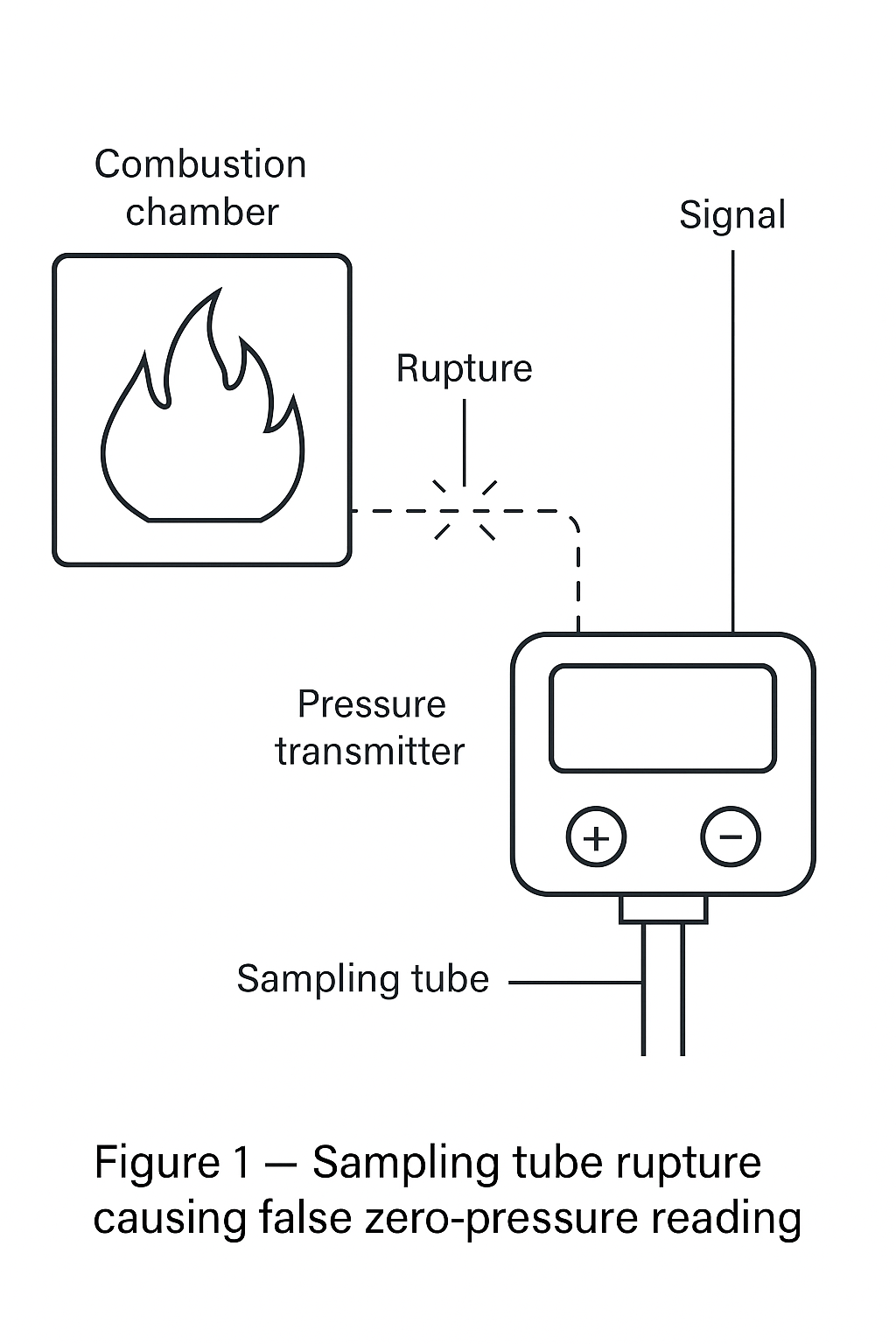
Reading too low | Water ingress, leakage | Inspect terminal box & impulse line |
Zero drift | Mounting orientation, parameter error | Adjust zero, reset range |
Output >20 mA | Internal electronics failure | Replace transmitter |
5. Conclusion
By classifying typical failures into impulse line issues, electrical problems, calibration errors, and hardware failures, maintenance personnel can quickly locate the root cause and perform corrective actions.
This structured troubleshooting approach reduces downtime, prevents misjudgment, and ensures stable process operation.