1. Measurement Principle
Principle:
High-frequency microwave pulses issued by the guided wave radar propagate along with detection components (steel cable or steel rod), met the media to be measured since the dielectric constant of the mutation, causes reflections, a portion of the pulse energy is reflected back. Transmit pulse and the reflected pulse is proportional to the distance and the time interval measured media.
Features:
As a result of advanced microprocessor and unique cho Discovery echo processing technology, guided wave radar level meter can be used in a variety of complex conditions.
Because of the type of process connections and detection components, making 70X Series Guided Wave Radar Level Meter is suitable for a variety of complex conditions and applications. Such as high temperature, high pressure, and low dielectric constant media.
Pulsed work, guided wave radar level instruments transmit power is very low, can be installed in a variety of metals, non-metallic container, no harm to humans and the environment.
Explanation:
Guided Wave Radar is a time travel to the principle of measuring instruments, radar runs at the speed of light, and the running time can be converted into a level signal by electronic components. When the pulse reaches the surface of the material, the pulse is reflected back and is received by the receiving container inside the instrument, the distance the signal is converted to level signals.
Reflected pulse signal along the cable or rod probe-type transmit to the instrument electronic circuit parts, the microprocessor processes the signal, identify the microwave pulse-echo generated in the material surface. Correct identification of the echo signal is completed the implementation by the pulse software, D, the distance from the material surface and the pulse travel time T is proportional:
D=C×T/2
Where C is the speed of light
Because the empty distance E is known, the level L is: 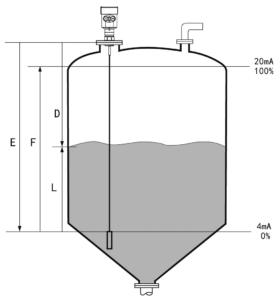
L=E-D
By entering the empty height of E (= zero), full tank height F (= hundred), and the application to set some parameters, application parameters will automatically adapt the instrument to measure the environment, corresponding to the 4-20mA output.
Measuring range:
Explanation:
H— Measuring range
L—Empty distance
B—The top of the blind
E—The minimum distance from the probe to the tank wall 
–Blindspot is the minimum distance between the top of the highest material surface materials and the measurement reference point.
–The bottom of the blind refers to a distance near the very bottom of the cable that can not be accurately measured.
–Between the top and bottom of the blind is a blind effective measure of distances.
Note:
In order to ensure the accuracy of level measurement, the material should be located between the top and bottom of the blind.
2、Product Introduction

Suitable for Medium: Liquid, solid powder
Application: Liquid and solid powder measure,
complicated process conditions
Explosion-proof Grade: Exia IIC T6 Ga/Exd IIC T6 Gb
Measuring Range: 30m
Frequency: 500MHz-1.8GHz
Antenna: Single cable or single rod antenna
Accuracy: ±10mm
Process Temperature:(-40~250)℃
Process pressure:(-0.1~4)MPa
Signal output:(4~20)mA/HART
The Scene Display: Four LCD/Can be programmed
Power Source: Two-wire (DC24V)
Four-wire(DC24V/AC220V)
Shell: Aluminum /Plastic
Connection: Flange (optional) / Thread
3、Installation Guide
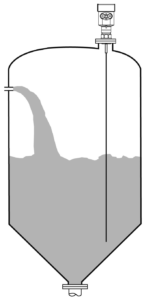
Within the measurement range, determined not to come into contact with the cable or rod internal obstacles, Therefore, the installation should be avoided as far as possible the tank facilities, such as a human ladder, limit switches, heating devices, stand, etc. Also, note that the cable or rod may not intersect with the material during feeding.
Also note that when installing the meter: the Highest Level measurement can not enter into the blind; Must be maintained between the instrument and the tank wall at a certain distance; When the meter is installed, try to stick with a cable or perpendicular to the surface of the measured medium. Meter installation in hazardous areas must comply with state regulations explosion hazardous installation areas. An intrinsically safe instrument requires the use of a shell with aluminum. The intrinsically safe instrument can be installed in explosion-proof requirements of the occasion, the instrument must be connected to the earth.

The measurement reference plane is the sealing surface of the thread.
- BlindRange (Menu 1.9)
- Cable Length (Menu 1.8)
- Measurement Range (Menu 1.2)
- Min. Measurement Range (Menu 1.1)
- reference plane
The following guidelines apply to the installation of the cable and the rod radar level measuring solid powder or liquid.
- Installation position:
- Far away from the discharge port and inlet.
- Metal cans in the entire measuring range, not to touch the tank wall and tank bottom.
The recommended meter is installed in 1/4 or 1/6 of the silo diameter, and the minimum distance is 1/10 of the tank wall of the measuring range.
- Cable type or rod probe the minimum distance from the tank wall ≥300mm.
- Bottom of the probe from the tank bottom ≥30mm.
- The minimum distance from the probe obstructions is≥200mm.
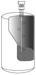
- If the bottom of the container is a cone, you can install a central tank top.

- Below is a single rod radar level meter installation drawings, mainly used for liquid level measurement
Features:
- You can measure any dielectric permittivity of ≥1.8.
- Generally used to measure viscosity ≤500cst, not prone to adhesion medium.
- Rod radar maximum range of 6 m.
- Instrumentation for steam and foam has strong penetrating power, the measurement is not affected.
- For a lot of foam liquid measurement environments, you should select a single rod guided wave radar level meter.
For more details, pls check the following user manual for reference.