How they work
The electromagnetic flowmeter utilizes the same principle as the electrical generator: when a conductor moves across a magnetic field a voltage is induced in the conductor, and the magnitude of the voltage is directly proportional to the speed of the moving conductor. If the conductor is a section of conductive liquid flowing in a non-conductive pipe through a magnetic field, and electrodes are mounted in the pipe wall at the positions shown in Figure 6.1. the voltage induced across the electrodes should be proportional to the flow rate.
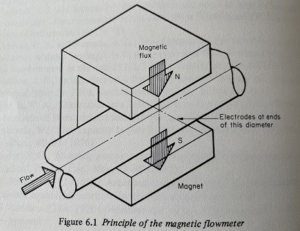
In such a situation, provided that the velocity profile is symmetrical and the magnetic field is uniform over a fairly long section of the pipe, a simple mathematical analysis reveals that
u=bvd
where U is the induced voltage, B is the magnetic flux density, v is the mean velocity of flow, and D is the pipe diameter.
In reality, magnetic fields are not completely uniform and flow profiles are not perfectly symmetrical. For this reason, the exact mathematical analysis of practical electromagnetic flow meters is extremely difficult, and if high accuracy is to be obtained from them they need to be calibrated just like any other flow meter.
There are also a number of practical problems which have to be taken into account in designing these meters, and so high-quality electromagnetic flowmeters are a great deal more complex than the simple situation of Figure 6.1 might suggest.
The main difficulties are as follows.
(a) At practical flow velocities, the value of the induced voltage is very small and hence difficult to measure accurately, especially if “stray” voltages are not completely eliminated.
(b) Mains voltage and frequency are never completely stable, and unless the circuit is designed to compensate for these input fluctuations they will give rise to spurious output fluctuations.
(c) Ordinary direct current cannot be used to power the electromagnets without causing polarisation of the electrodes, but if (as was always the case until fairly recently) ordinary alternating current is used, this causes a kind of transformer effect which generates troublesome out-of-phase voltages.
(d) It is difficult to obtain a completely stable electrical zero; in other words, “zero drift” can be a serious problem, especially in the older types of electromagnetic flowmeter.
(e) Some liquids quickly foul the electrodes, thereby causing the meter to give false readings unless remedial action is taken.
Complicated circuitry has proved necessary to deal with these problems. Recently it has been found that square-wave alternating current(sometimes known as pulsed direct current) provides a good way of dealing with problems(c) and (d). Built-in ultrasonic devices for cleaning the electrodes automatically are the most popular way of dealing with (e), although electrolytic cleaning or mechanical wipers are sometimes used instead.
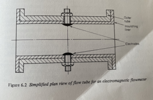
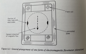
The mechanical construction of a typical meter is shown diagrammatically in Figures 6.2 and 6.3. To avoid shorting the electrodes the meter has to have an insulating liner (Figure 6.2). To avoid shorting coils are sited at 90° from the electrodes and the whole assembly is, in this particular design, encased by a laminated yoke (Figure 6.3). The selection of materials for the insulating liner and the electrodes is quite important, and it is usual for meters to be almost tailor-made for the particular liquid, temperature and pressure envisaged.
Advantages
(a) There is no obstruction whatever to the flow, and electromagnetic flowmeters are therefore well suited for measuring heavy suspensions, including mud sewage and wood pulp.
(b) They have a zero effective head loss-which means that the loss is no more than that of the length of straight pipe which the meter replaces. This makes it a suitable meter for large water-supply pipelines, where low head loss is essential.
(c) Industrial electromagnetic meters are made over a wider range of sizes than almost any other type of meter, namely, from about 3mm to about 3 m diameters.
(d) Electromagnetic meters are not too seriously affected by upstream flow disturbances unless severe asymmetry of the velocity profile is present.
(e) They are practically unaffected by variations in density, viscosity, pressure, temperature, and (within limits) electrical conductivity.
(f) Range-switching circuits are available which enable one meter to be used over a very wide range of flow rates(much more than the usual 10:1). although accuracies may be poor at the low end of a particular metering range.
(g) The output is essentially linear.
(h) These instruments are naturally bi-directional in operation and hence can be used for the measurement of reversing or pulsating flow, provided that the frequency of pulsation is well below the frequency of the magnetic field excitation.
(i) Special instruments for measuring the flow of some molten metals are available, although it may be necessary to go to a specialist manufacturer for these.
(j) Other highly specialized electromagnetic meters are made for measuring flow in the human blood vessels.
Disadvantages
(a) The liquid to be metered must have a reasonable electrical conductivity. Just what constitutes “reasonable” is a matter of controversy; electromagnetic meters can be built to cope with liquids having as low conductivity as 0.1 umho cm-1, but these are highly sophisticated and costly devices. For ordinary industrial purposes, the practical limit is more like 10 umho cm-1; this means that water-based liquids can be handled comfortably, but hydrocarbons and most other organic liquids cannot.
(b) Although modern electromagnetic meters are considerably better than those of a few years ago, they are still not among the most accurate flow meters. About the best accuracy obtainable today from the general run of electromagnetic flowmeters is ±1% over a flow rate range of 5:1, with accuracies falling off considerably at flow rates below 20% of full scale. A few manufacturers now offer super-quality meters with a claimed accuracy of ±0.5% over a 5:a range, but these are expensive, and it remains to be seen whether such accuracies can be maintained over a long period in industrial service.
(c) The size and cost of the field coils and circuity do not increase in proportion to the size of the meter; consequently, although large electromagnetic meters are undoubtedly good value for money, with decreasing pipe sizes the meters become relatively more and more bulky and expensive.