1. Common Grounding Methods for Shield Layers
In industrial applications, shielded cables are typically grounded in one of two ways:
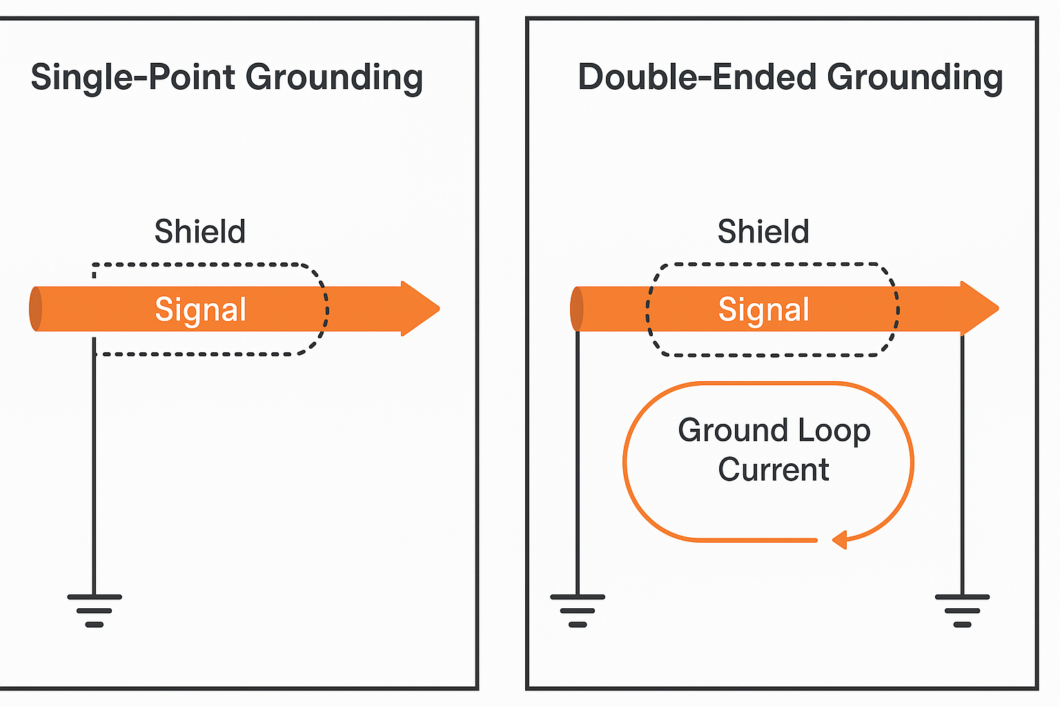
(1) Single-Point Grounding (Recommended for Control Systems)
The metallic shield is grounded only at one end, while the other end is left unconnected or grounded via protective earth.
✅ Purpose: To eliminate electromagnetic interference (EMI) by preventing potential difference-induced currents.
⚠️ Limitation: Best suited for short cable runs—induced voltage must remain below the safety threshold.
(2) Double-Ended Grounding
The shield layer is grounded at both ends of the cable.
✅ Effectiveness: Prevents induced voltages on the shield.
⚠️ Risk: If the ground potentials at both ends (e.g., Point A and Point B) are not equal, it creates ground loop currents. These circulating currents may interfere with the signal and cause attenuation or signal distortion.
📌 Suggested Diagram 1:
Compare single-ended vs. double-ended grounding with arrows showing signal flow and ground loop current path.
2. Why Multi-Point Grounding Should Be Avoided
When shield layers are grounded at multiple locations, especially in environments with varying ground potentials, the resulting ground loop can act as an antenna—inducing noise currents that compromise the integrity of transmitted signals. This is particularly critical in low-voltage, high-speed signal systems such as PLCs or DCS.
3. Grounding Strategy for PLC/DCS Systems
PLC (Programmable Logic Controller) and DCS (Distributed Control System) are sensitive to signal noise due to their low-voltage and high-frequency characteristics. Proper grounding is essential.
(1) Preferred System Grounding Type
Direct grounding is ideal for PLC/DCS systems, avoiding floating or capacitive grounding.
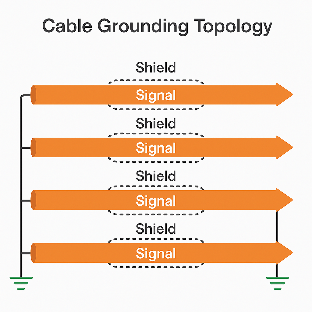
(2) Recommended Grounding Topologies
Single-point grounding or serial single-point grounding is preferred.
For centrally installed PLC/DCS units:
Use parallel single-point grounding: each cabinet’s central ground connects individually to a common ground electrode.
For widely spaced units:
Use serial grounding with a large cross-section copper bar or insulated cable linking all cabinet grounds, then connect the main bus to earth.
(3) Signal Cable Shielding Best Practices
If the signal source is grounded: ground the shield on the signal side.
If the source is floating: ground the shield at the PLC/DCS side.
If connectors or splices are present: ensure shields are bonded and insulated, and avoid additional grounding points.
📌 Suggested Diagram 2:
Cabinet grounding layout: parallel vs. serial grounding
📌 Suggested Diagram 3:Signal cable with splice and shield continuity
4. Conclusion
Avoiding multiple grounding points for shielded cables is essential to:
Prevent ground loop currents
Minimize signal distortion
Ensure EMI suppression
Maintain stable and accurate operation of control systems
For robust PLC/DCS system performance, adopt a single-point grounding strategy with proper shield termination, tailored to your layout and signal characteristics.