Understanding the Principles Behind 3-Wire and 4-Wire Resistance Temperature Detectors (RTDs)
1. Overview
RTDs (Resistance Temperature Detectors) measure temperature based on the principle that a metal’s resistance changes with temperature. However, when connecting an RTD to an instrument located at a distance, the resistance of the lead wires can introduce significant measurement errors. To reduce or eliminate this influence, different wiring methods are used — with the 3-wire and 4-wire configurations being the most common.
2. The 3-Wire RTD Configuration
2.1 Measurement Principle
A 3-wire RTD includes three lead wires: one connected to one end of the RTD element, and the other two to the opposite end. This configuration is designed to reduce the error caused by the lead wire resistance.
2.2 The Problem: Lead Wire Resistance
When an RTD is connected to a measurement system via long cables, the resistance of these cables adds to the total resistance being measured. This introduces errors in temperature readings, especially in precision applications.
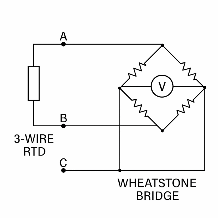
2.3 How the 3-Wire System Works
The 3-wire method is commonly used with a Wheatstone bridge circuit:
Two wires (let’s call them A and B) are connected to opposite ends of the RTD and incorporated into different arms of the bridge.
The third wire (C) acts as a reference or common return.
Since wires A and B are assumed to have identical resistance, the bridge circuit can cancel out their effects during balance calculation.
✅ Advantage: This method compensates for lead wire resistance under the assumption that the two lead wires have equal resistance — suitable for general industrial use.
3. The 4-Wire RTD Configuration
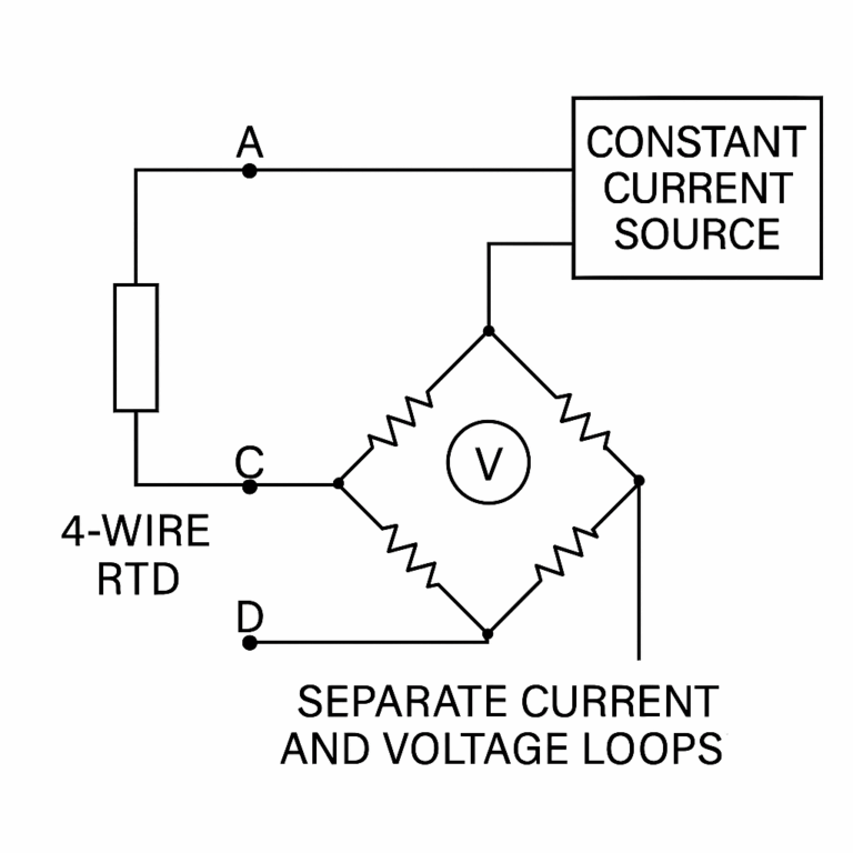
3.1 Structure and Wiring
The 4-wire RTD separates the current-carrying and voltage-sensing functions:
Two wires are used to supply a constant current (connected to a current source).
Two additional wires are used solely to sense the voltage across the RTD.
3.2 Elimination of Resistance Error
Lead wire resistance in the current loop may cause voltage drop, but it does not affect the voltage sensing wires.
Voltage sensing wires are connected to a high-impedance voltmeter, meaning minimal current flows through them — thus, their resistance contributes negligible voltage drop.
✅ Advantage: This method eliminates the influence of both lead wire resistance and contact resistance, resulting in highly accurate temperature readings.
3.3 Ideal Use Cases
Precision laboratory measurements
High-end industrial process control
Situations requiring accuracy better than ±0.1°C
4. Comparison: 3-Wire vs. 4-Wire RTD
| Feature | 3-Wire RTD | 4-Wire RTD |
|---|---|---|
| Lead Wire Compensation | Partial (assumes equal resistance) | Full (independent current/voltage) |
| Measurement Accuracy | Medium (±0.2 to ±0.5°C typical) | High (±0.05 to ±0.1°C possible) |
| Cost & Complexity | Moderate | Higher |
| Typical Applications | Industrial automation, DCS inputs | Labs, R&D, critical process control |
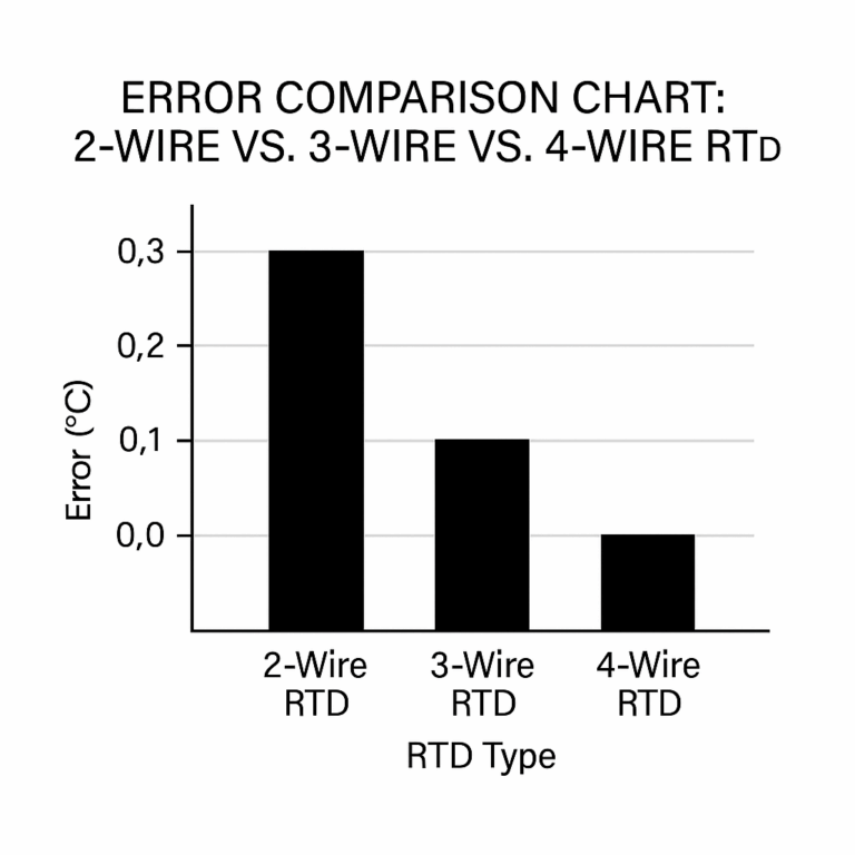
5. Conclusion
The 3-wire RTD provides a good balance between cost and measurement accuracy for most industrial applications. However, when maximum precision is required — especially over long cable runs or in environments where even small errors matter — the 4-wire RTD offers the most accurate solution by design.