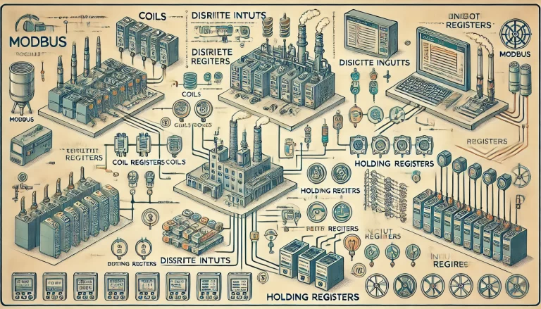
The Modbus protocol, developed in the late 1970s by Modicon, is widely used for industrial automation and control systems. A key feature of Modbus is its straightforward data structure, centered around four types of data registers. These registers facilitate the transfer of both digital (binary) and analog data between different devices, such as programmable logic controllers (PLCs), sensors, and actuators, enabling seamless industrial communication.
Here, we delve into the four types of Modbus registers—Coils, Discrete Inputs, Holding Registers, and Input Registers—their functions, characteristics, and how they enable efficient data exchange within a Modbus network.

1. Coil Registers
Coil registers are binary data registers typically used to manage output states in a Modbus system. They can be either written to (set or reset) or read, depending on the application’s needs.
- Purpose: Coil registers store single-bit data, which represents the state of a switch or a relay (0 for “off,” 1 for “on”). They’re commonly used for turning devices on and off.
- Address Range: 00001 – 09999.
- Function Codes:
- 01: Read Coils
- 05: Write Single Coil
- 15: Write Multiple Coils
Coils are the basis for controlling the on/off state of various industrial equipment. A PLC can use a coil register to turn a device, such as a motor or pump, on or off. For example, a register value of 1 might signal to activate a motor, while a 0 would shut it down. In Modbus communication, multiple coils can be managed at once, making it efficient for large-scale control operations.

2. Discrete Input Registers
Discrete input registers, also referred to as “Input Status” registers, are read-only and used to monitor the state of digital inputs from external devices.
- Purpose: Discrete input registers are also single-bit, representing binary data that typically corresponds to input sensors or switches. These registers allow the Modbus master to read the state of an external device without altering it.
- Address Range: 10001 – 19999.
- Function Code: 02 (Read Discrete Inputs)
Discrete inputs are ideal for monitoring sensors, such as limit switches or emergency stop buttons, that only need to be read by the Modbus master. For instance, a discrete input register could represent whether a safety gate is open (0) or closed (1). These registers are foundational for monitoring physical inputs in a system without impacting their state.

3. Holding Registers
Holding registers are the most versatile data registers within the Modbus protocol. They can hold 16-bit analog or numerical values and support both read and write functions, making them adaptable to a wide range of applications.
- Purpose: These registers store data values for settings, control parameters, and other numerical data that may require adjustments or monitoring, such as temperature set points, flow rates, and more.
- Address Range: 40001 – 49999.
- Function Codes:
- 03: Read Holding Registers
- 06: Write Single Register
- 16: Write Multiple Registers
A single holding register can store an unsigned 16-bit integer value ranging from 0 to 65,535. Multiple registers can be combined to store larger values or different data types, such as floating-point numbers. Holding registers are essential in applications requiring adjustable parameters, where the Modbus master device can alter system settings dynamically. For example, adjusting a thermostat’s temperature setpoint in a heating control system would involve writing to a holding register.

4. Input Registers
Input registers are similar to holding registers in structure but are strictly read-only. These registers are often used to collect real-time measurement data from sensors or instruments connected to the Modbus network.
- Purpose: Input registers store 16-bit analog input values (e.g., pressure, voltage, temperature) generated by sensors or other field devices. Since they are read-only, they are used for data collection rather than control.
- Address Range: 30001 – 39999.
- Function Code: 04 (Read Input Registers)
In a monitoring application, an input register might store data from a pressure sensor measuring a system’s PSI. The Modbus master device can then read this data for analysis or logging without modifying it. Input registers are vital for monitoring key system parameters in real time, allowing operators to track performance and detect issues promptly.
Practical Example: Modbus Register Usage in an Industrial Application
Consider a manufacturing plant using a Modbus system to control and monitor a mixing tank. Here’s how each register type might be used:
- Coil Register: The plant operator can activate or deactivate the mixing motor by writing to a coil register. Setting the coil to 1 starts the motor; setting it to 0 stops it.
- Discrete Input Register: A limit switch on the tank lid can be read from a discrete input register. If the lid is open, the register value is 1; if closed, it’s 0, signaling whether it’s safe to operate the mixer.
- Holding Register: The target mixing temperature might be set through a holding register. The operator could write a new temperature value as needed, allowing for flexible control.
- Input Register: The actual temperature inside the tank can be read from an input register connected to a temperature sensor, providing live data for monitoring and ensuring the setpoint is maintained.

Conclusion
Modbus registers are the backbone of the Modbus protocol, providing a structured way to handle binary and analog data in a simple, reliable format. Coil and Discrete Input registers serve binary (on/off) data, while Holding and Input registers manage analog values, with Holding Registers adding the flexibility of writable data.
Understanding how to use each type of register enables the development of efficient and scalable industrial control systems, allowing engineers to monitor, adjust, and control processes with ease.
