1. Introduction
Importance of correct impulse line installation for measurement accuracy, safety, and long-term reliability.
Typical consequences of improper installation: gas/liquid accumulation, measurement drift, leakage, or instrument damage.
2. Adaptation to Process Media
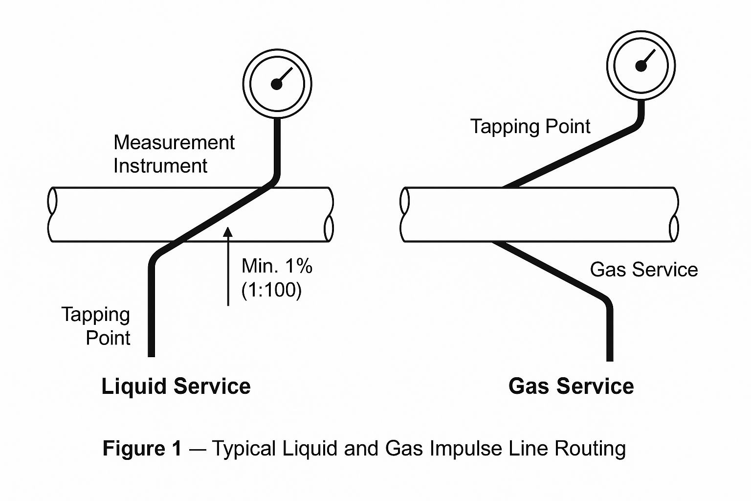
2.1 Liquid Service
Impulse lines should slope toward the instrument with a minimum gradient of 1:100 to prevent gas accumulation.
Pressure tapping point should be located at the lower side of the pipeline to avoid entrained gas.
2.2 Gas Service
Impulse lines should slope toward the tapping point to prevent liquid accumulation.
Pressure tapping point should be located at the upper side of the pipeline to avoid condensate interference.
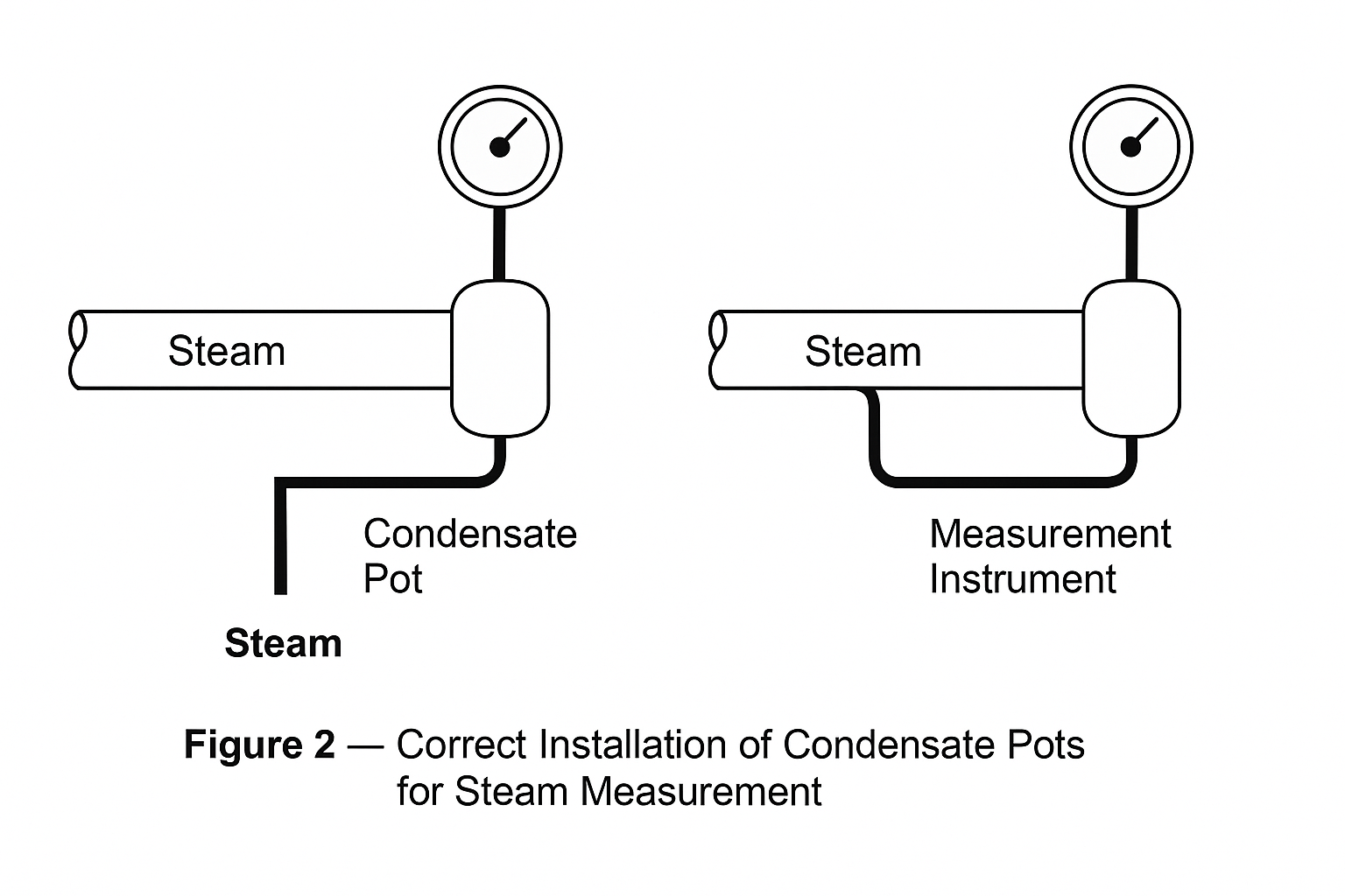
2.3 Steam Service
Install a condensate pot near the tapping point; ensure impulse lines remain filled with water to protect the instrument from high-temperature steam.
Lines should be level or slightly sloped toward the condensate pot to minimize thermal effects.
2.4 Corrosive Media
Select corrosion-resistant materials (e.g., stainless steel, PTFE).
Avoid welded joints; prefer flanged or threaded connections.
3. Ensuring Measurement Accuracy
Impulse line length and diameter: ≤ 50 m; 6–10 mm ID recommended to reduce lag and response delay.
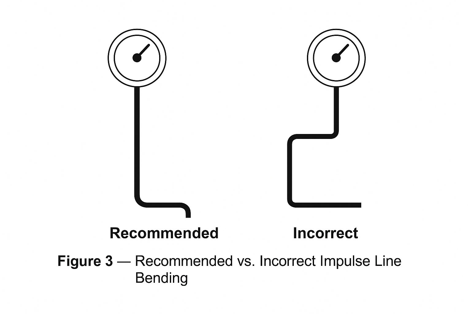
Avoid sharp bends; use smooth radius curves to minimize resistance and vortex effects.
For differential pressure measurements, impulse lines must be laid in parallel with equal length and temperature exposure to prevent density imbalance.
Keep lines away from vibration sources (pumps, blowers) and strong electromagnetic fields (motors, transformers). Use supports and damping where necessary.
4. Installation Location and Routing
Install impulse lines in accessible locations for inspection and maintenance.
Protect outdoor installations with weatherproofing and thermal insulation (e.g., tracing, jackets).
Avoid tapping at weld seams, valves, or elbows; select straight pipe sections with at least 10D upstream and 5D downstream of the tapping point.
Maintain at least 150 mm clearance from other pipelines and equipment.
5. Connection and Sealing Requirements
Welded and flanged connections: free from porosity and slag; gasket material must match the process conditions (metallic gaskets for high temperature, elastomers for low pressure).
Threaded connections: use PTFE tape or sealant to ensure leak tightness.
High-pressure or hazardous media: impulse lines and valves must be supported; joints should be reinforced and equipped with leak-detection systems if required.
6. Valves and Accessories
Primary (root) valve: installed close to the tapping point;
Secondary valve: near the instrument.
Valves should be oriented with flow direction and fixed independently in high-pressure systems.
Install vent valves at the highest point (for liquid service) or drain valves at the lowest point (for gas service) to remove air pockets or condensate.
Table 1 — Installation Differences for Liquid, Gas, and Steam Services
| Item | Liquid Service | Gas Service | Steam Service |
|---|---|---|---|
| Impulse Line Slope | Toward the instrument, min. 1:100 (downward slope) | Toward the tapping point, min. 1:100 (upward slope) | Slightly sloped toward condensate pot |
| Tapping Point Location | Bottom of the pipeline (to avoid gas pockets) | Top of the pipeline (to avoid condensate accumulation) | Side or top of pipe with condensate pots installed near tapping points |
| Condensate Management | Not required | Drain valves at low points to remove liquid | Condensate pots to maintain equal water column |
| Risk of Error | Gas accumulation in impulse line | Liquid accumulation causing false readings | Thermal damage to transmitter if no condensate pot is used |
| Recommended Accessories | Air vent at the highest point | Drain valve at the lowest point | Condensate pot, thermal insulation, steam tracing if necessary |
| Special Notes | Ensure no air pockets remain | Ensure complete drainage of liquid from impulse lines | Keep both condensate pots at the same elevation to balance DP measurement |
7. Testing and Identification
Perform tightness testing (hydrostatic or pneumatic) according to system pressure rating. No leakage or pressure drop should occur during the test period.
Impulse lines should be clearly labeled with medium name and flow direction.
High-/low-temperature lines should carry warning signs.
Buried or concealed lines should have positioning records for maintenance.
8. Conclusion
Proper installation of impulse lines is essential to:
Ensure stable and accurate measurement signals.
Protect instruments from damage caused by high temperature, pressure, or corrosive media.
Reduce maintenance workload and improve system safety.