These guidelines provide step-by-step instructions and safety considerations for the maintenance, troubleshooting, and calibration of ultrasonic and radar level transmitters. Proper execution of these procedures will help ensure measurement accuracy, extend service life, and minimize equipment failures.
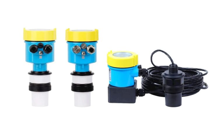
1. Ultrasonic Level Transmitter Maintenance
1.1 Pre-Maintenance Preparation
Understand Operating Conditions:
Identify the measured medium’s characteristics (e.g., corrosiveness, temperature, pressure).
Note installation type (flanged, threaded) and environment (dust, vibration, electromagnetic interference).
Review historical fault records for common issues like probe fouling or signal interference.
Visual Inspection Checklist:
Ensure the device is dry, intact, and free from corrosion.
Check whether the terminal box is sealed, wiring terminals are corrosion-free, and the display panel functions normally.
Confirm protective covers (e.g., sun/rain shields) are in good condition.
Safety Considerations:
Power off the device before any operation.
In explosive atmospheres, ensure compliance with explosion-proof standards and use explosion-proof tools.
Use safety harnesses for elevated work and set up warning signage.
Tools & Spare Parts:
Multimeter, oscilloscope, calibration kit (e.g., simulated level devices), soft cloth, anhydrous alcohol, spare probes, circuit boards, etc.
1.2 On-Site Maintenance Procedure
External Inspection:
Clean probe surfaces using a soft cloth and alcohol. Do not scrape with hard objects.
Check for dirt, scaling, or corrosion on radar antennas or guided wave cables.
For guided wave level transmitters, ensure the waveguide tube is clean and free of foreign matter or deformation.
Electrical Testing:
Measure supply voltage (typically 24VDC or 220VAC) and check output signals (4–20mA or RS485) for stability.
Use an oscilloscope to examine ultrasonic transmission and reception waveforms. Distortions or low amplitudes may indicate aging probes or circuit issues.
Installation Check:
Ensure the probe is vertically aligned with the liquid surface.
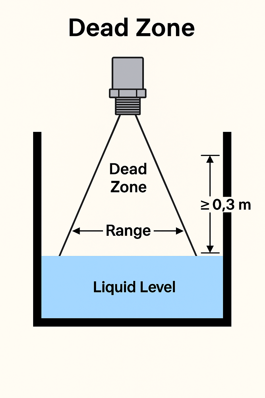
Maintain a sufficient distance from container walls to avoid echo interference (distance should exceed the blind zone).
Simulated Calibration:
In the absence of actual liquid, use a simulator or input reference values through programming to verify reading accuracy (±0.5% FS typical).
If out of range, recalibrate or adjust parameters (e.g., sound velocity compensation, blind zone setting).
1.3 Installation Considerations
Mount the radar transmitter vertically with a horizontal flange.
For guided wave radars, inspect openings for burrs or welding slag before installation; maintain precise verticality.
For cable-type radars, avoid knots or contact with vessel walls. Cut and secure cable ends if excessively long.
Clean the flange sealing surface and align gaskets properly; ensure bolts extend through both sides.
After installation:
Check device configuration and echo quality.
Perform signal suppression as needed.
Simulate current output to verify control room readings.
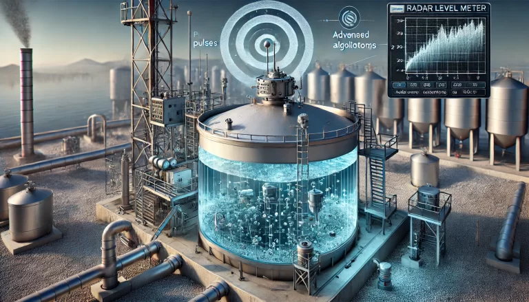
2. Radar Level Transmitter Maintenance
2.1 Pre-Maintenance Preparation
Working Condition Assessment:
Determine the dielectric constant (εr) of the medium, temperature, pressure, and presence of steam or fog.
Identify radar type (e.g., pulse radar or FMCW—Frequency Modulated Continuous Wave radar).
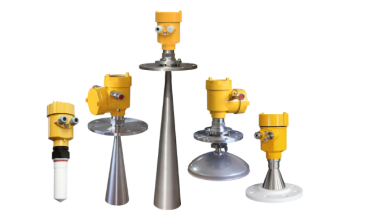
Confirm installation method (threaded, flanged, hygienic interface) and antenna type (horn, parabolic, guided wave).
Safety & Tools:
In hazardous areas, ensure power is disconnected. Explosion-proof tools must be used.
Never disassemble the antenna while powered on.
Prepare tools such as a multimeter, signal generator, dielectric calibration kit, laser rangefinder, spare antennas, and circuit boards.

2.2 Maintenance Procedure
Appearance & Installation Check:
Inspect the antenna for buildup, condensation, or foreign matter—especially for horn antennas.
Use a soft brush to clean without damaging the coating.
Check antenna spacing from tank walls to avoid signal reflection. For guided wave radar, verify vertical alignment and cable/rod integrity.
Electrical & Signal Testing:
Verify power supply voltage and check output (4–20 mA or HART).
Use a handheld communicator (e.g., Rosemount 275) to read parameters and view echo curves.
Analyze echo patterns: weak or multiple reflections may suggest dirty antennas, poor installation, or medium variation (e.g., dielectric changes).
Parameter Calibration:
For pulse radar: verify settings like range, blind zone, and tank reference.
For FMCW radar: calibrate signal frequency and phase as needed.
If the medium has changed, reset the dielectric constant or perform empty-tank calibration using “false echo suppression.”
Simulated Testing:
Use a signal generator to simulate level signals and verify response accuracy.
For guided wave radar, use a laser rangefinder to compare actual level with displayed value.
2.3 Post-Maintenance Commissioning
Functional Verification:
Restore power and ensure the device initializes correctly.
Confirm that the echo curve is sharp and the main echo appears in the correct range.
Performance Testing:
Simulate level changes to confirm linear output correlation. Target error:
±0.1% FS for high-precision models
±0.5% FS for standard models
Environmental Adaptation:
In high-temperature or steam environments, check if condensation affects the antenna (install anti-condensation hoods if needed).
For low dielectric materials (e.g., oil, LPG), ensure antenna type is suitable (e.g., parabolic antenna).
Documentation & Sealing:
Record calibration parameters, echo curve patterns, and any replaced parts.
Apply waterproof sealing (e.g., silicone sealant) at antenna interfaces to prevent ingress.

3. General Maintenance Considerations
Corrosion Protection:
For corrosive media, ensure wetted parts (e.g., probe, flange) are made of suitable materials like stainless steel or PTFE.
Replace any corroded components promptly.
Data Backup:
Always back up instrument parameters (e.g., range, calibration factors) before performing any operations.
Personnel Qualification:
Only qualified personnel or authorized service teams should handle calibration involving explosion-proof devices or dielectric constant adjustments.
Conclusion
By following these detailed procedures and safety protocols, maintenance personnel can ensure reliable operation, improved measurement accuracy, and extended service life for both ultrasonic and radar level transmitters. Regular inspection and proper documentation are essential for long-term system performance.