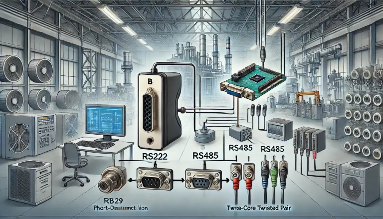
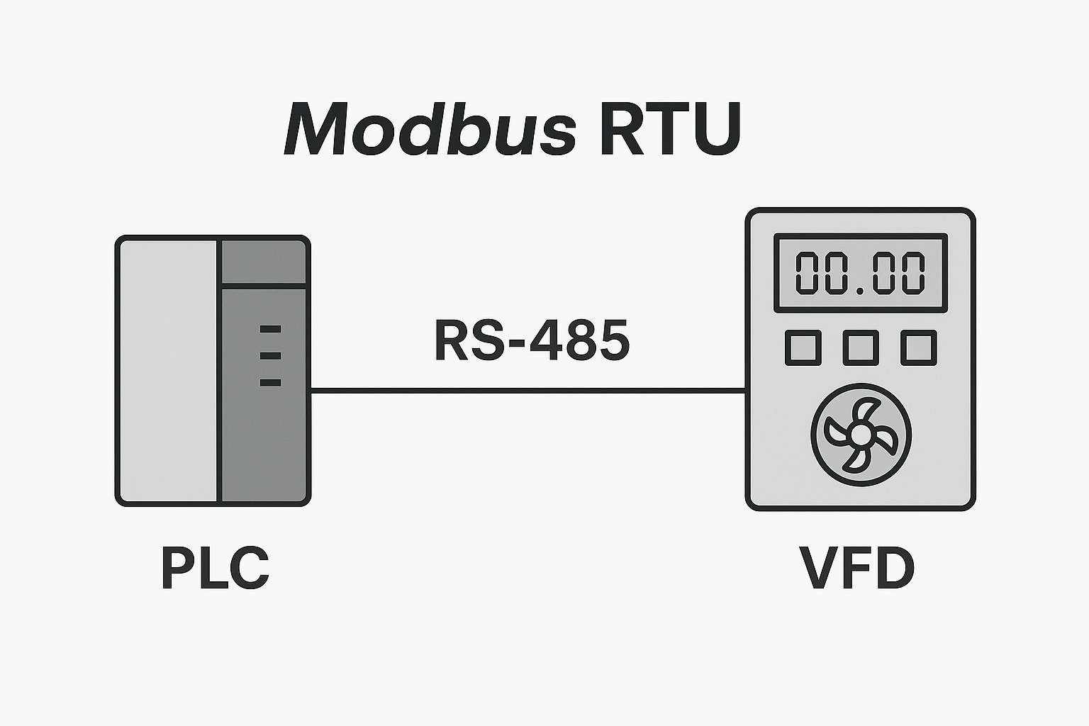
RS-485 communication is widely used in industrial control and building automation due to its differential transmission, long-distance capability, and strong noise immunity. However, one critical factor often overlooked is loop impedance. Poor impedance design can lead to packet loss, communication errors, and frustrating troubleshooting.
This guide breaks down what loop impedance is, why it matters, and how to optimize it in real-world RS-485 systems — making your communication network as smooth as a highway.
1. What Is Loop Impedance?
Imagine a household water supply system: the pump (transmitter) pushes water to various taps (receivers), then the water returns to the pump — forming a loop. The pipe diameter, elbows, valves, and pressure all affect flow efficiency.
Similarly, in RS-485 communication, loop impedance refers to the total opposition a signal faces as it travels from the transmitter, through the twisted pair cable, into the receiver, and back via the return path.
It consists of:
Resistance (R) — Like pipe friction from narrow diameters.
Inductance (L) — Like valves and bends that slow water changes.
Capacitance (C) — Like storage tanks that delay flow response.
These factors combined form the overall AC impedance affecting RS-485 signal integrity.
2. What Makes Up the Loop Impedance?
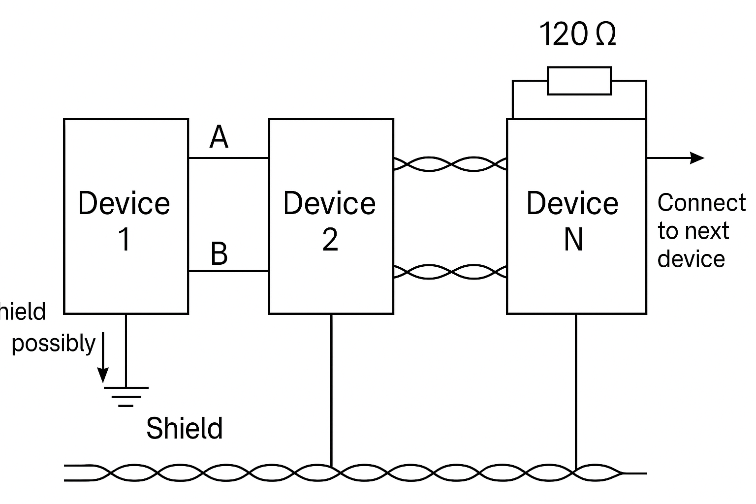
Cable Characteristic Impedance (~120 Ω) RS-485 typically uses shielded twisted-pair cables with a nominal impedance of 120 Ω, much like choosing a uniform pipe size to ensure even water flow.
Termination Resistors A 120 Ω resistor at both ends of the bus absorbs signal energy, preventing reflection — much like installing dampers in a pipeline to stop water hammer.
Receiver Input Impedance (in Multi-Drop Networks) Multiple devices connected to the same bus reduce total input impedance, like adding too many branches to a pipe and weakening pressure at the end.
Connectors and Protection Devices Each connector or TVS diode introduces slight impedance discontinuities — think of them as pipe joints where small leaks or blockages may form.
Common-Mode Loop and Grounding RS-485 is differential, but the ground path still matters. Ground potential differences between devices can create noise currents, similar to uneven water levels between tanks causing backflow.
3. Why Is Impedance Continuity So Important?
Signal Integrity Impedance mismatch causes signal reflections, ringing, and overshoot — making it difficult for the receiver to distinguish logical 1s and 0s.
Transmission Distance and Speed Poor impedance equals greater signal loss over distance or at high baud rates.
EMI Susceptibility Discontinuities act like “cracks” where external electromagnetic noise can enter more easily.
Power Consumption & Device Life The driver compensates for poor transmission by pushing more current — increasing heat, power usage, and reducing component lifespan.
4. Best Practices for Design and Optimization
Golden Rule: Maintain continuous and uniform impedance — like building a straight, smooth highway without sharp turns or unnecessary exits.
✔ Cable Selection
Use 120 Ω shielded twisted-pair cable.
Ensure the shield is properly grounded (either one-end or both-end grounding depending on EMI risk).
✔ Routing Guidelines
Keep differential pairs equal in length and spacing.
On PCBs, avoid routing across split ground planes. Use a continuous ground reference.
✔ Termination and Split-Termination
Install a 120 Ω resistor at each physical end of the bus.
For better common-mode suppression, consider split termination (two 60 Ω resistors with a capacitor to ground at the midpoint).
✔ Fail-Safe Biasing
Use external pull-up/down resistors to keep the bus in a known logic state when idle.
Do not rely solely on the internal fail-safe of RS-485 transceivers.
✔ Topology Matters
Use a linear bus topology (daisy-chain).
Avoid star or ring topologies and minimize stub lengths.
✔ Slew Rate Control
Slower edge transitions reduce reflections.
For long distances, use transceivers with controlled slew rate or reduce the baud rate.
5. Debugging and Validation Tips
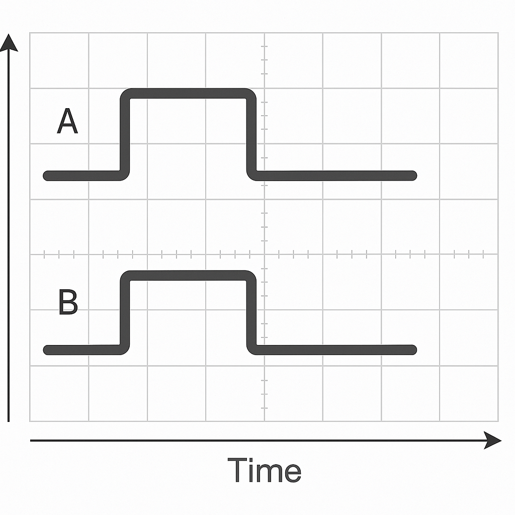
Oscilloscope Analysis Use differential probes to observe A/B lines. Look for ringing, overshoot, or attenuation that indicates mismatch.
Segment Isolation Disconnect branches one by one to locate sources of impedance issues.
Trial-and-Error Optimization Replace suspect cables, adjust terminations, or add common-mode chokes to test improvements.
EMI/ESD Protection Use well-rated TVS diodes and chokes with low parasitic effects to maintain impedance balance while protecting against surges.
6. Common Engineering Mistakes to Avoid
Terminating only one end of the bus.
Installing terminators in the wrong position (not at physical ends).
Using too many or too long stubs.
Selecting non-120 Ω cables.
Ignoring ground potential differences.
Relying solely on internal fail-safe circuits.
7. Quick Checklist
Item
Requirement
Cable
120 Ω shielded twisted pair
Routing
Equal length, spacing, and proper grounding
Termination
120 Ω at each end (or split termination)
Stubs
Keep to minimum; short and few
Biasing
External pull-up/down resistors for idle bus state
Protection
TVS diodes and chokes selected for minimal parasitics
Testing
Clean oscilloscope waveforms with minimal ringing
Grounding
Avoid ground loops and ensure proper bonding
8. Conclusion
Loop impedance is the “vascular elasticity” of your communication system. When impedance is consistent and continuous, signals flow smoothly and reliably.
Whether you’re designing a factory automation system or a smart building network, keeping loop impedance under control is the key to unlocking the full potential of RS-485.