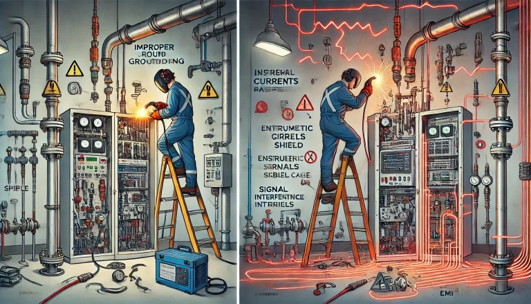
In chemical production environments, instrumentation systems serve as the “eyes and brain” for monitoring and controlling processes, while grounding systems act as the “lifeline” for operational safety and stability. Improper grounding can result in signal interference, data distortion, or even catastrophic incidents such as fires and explosions.
Grounding is essential for:
✅ Safety Protection
Prevent lightning damage and static buildup.
Eliminate electrical sparks in explosive environments (e.g., Ex areas).
Protect personnel from electric shocks.
✅ Functional Reliability
Reduce electromagnetic interference (EMI) and ensure accurate signal transmission (e.g., 4–20mA loops).
Eliminate common-mode voltage hazards to the control system.
2. Four Types of Grounding in Chemical Instrumentation
Type
Purpose
Key Requirements
Application Scope
Signal Grounding
Reference voltage level, EMI reduction
≤1Ω resistance, copper wire recommended
Analog/digital signal circuits
Protective Grounding
Prevents electrical hazards to personnel
≤4Ω resistance, shared with electrical grounding mesh
Electrical cabinet shells, instrument panels
Static Grounding
Prevent static discharge in flammable areas
Independent ground rod, ≤100Ω
Pipes, tanks with flammable/explosive media
Lightning Grounding
Diverts lightning current safely to ground
Integrated with lightning protection, ≤10Ω
Outdoor tanks, towers, process units
3. Design Standards and Best Practices
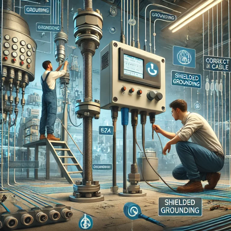
🧷 Grounding Material Selection
Prioritize copper conductors (corrosion-resistant, high conductivity)
Minimum cross-sectional area: ≥16mm² for multi-strand wires
Use galvanized flat steel ≥40mm×4mm for grounding main lines
🧪 Ground Resistance Requirements
Independent instrument grounding: ≤1Ω
Shared grounding: Must be co-designed with electrical systems
🔗 Equipotential Bonding
Interconnect all instrument cabinets, junction boxes, and metal conduits through a common ground bus
Eliminates voltage differentials between system components
🔒 Special Zones (Hazardous Areas)
Intrinsically safe systems must have a separate ground bus, isolated from non-intrinsically safe circuits
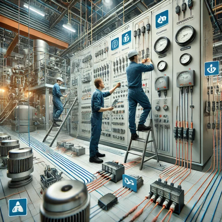
4. Installation and Inspection Guidelines
🔧 Installation Practices
Avoid routing ground wires parallel to power cables. If unavoidable, cross at 90°.
Ground rods should be buried ≥0.6m below surface (below frost line)
Apply grounding resistance-reducing agents as needed
🔍 Testing Requirements
Use professional testers such as Fluke 1625 for resistance verification
Avoid testing immediately after rain to prevent false readings
⚠️ Common Mistakes
❌ Direct welding of instrument cabinet to steel structure (introduces interference)
✅ Correct: Use insulating spacers and soft copper wires to connect to the ground bus
5. Maintenance and Grounding Integrity Management
Perform at least annual resistance testing, with additional checks before and after rainy seasons
Clear vegetation and debris near ground rods to reduce soil resistivity
Ground wires must be clearly marked (e.g., yellow-green) to prevent accidental disconnection
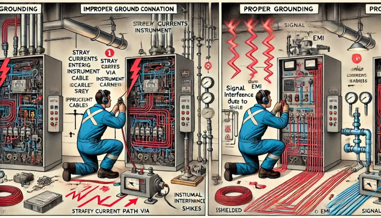
6. Real-World Incident: The Cost of Improper Grounding
At a chemical plant, a flow meter and a motor shared the same ground rod. When the motor leaked current, the signal system of the flow meter failed, causing a cascade shutdown of the production line.
Lesson Learned: Strictly separate grounding types to avoid interference and ensure system stability.