Differences Between PFD and P&ID - Just Measure it

Differences Between PFD and P&ID

In engineering fields such as chemical, petroleum, pharmaceutical, and power generation, two key technical diagrams are widely used: the Process Flow Diagram (PFD) and the Piping and Instrumentation Diagram (P&ID). Although closely related, they serve distinct purposes at different stages of a project.

1. What Is a PFD?

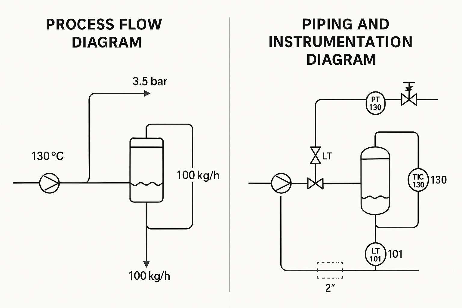
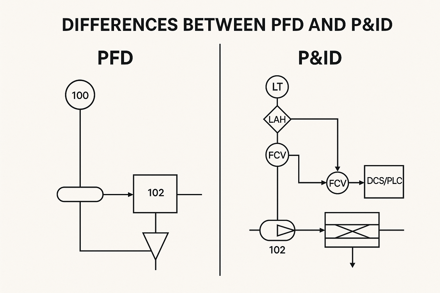
Definition:
A Process Flow Diagram (PFD) provides a high-level overview of the entire process flow. It outlines the primary equipment and the direction of material flows, along with key process parameters such as temperature, pressure, and flow rate.

Main Features:

  • Focuses on the main process route rather than equipment details

  • Displays major equipment such as reactors, heat exchangers, pumps, and compressors

  • Shows material flows, directions, and labels

  • May include mass or energy balances

  • Limited representation of control systems (basic control loops only)

  • Does not include safety valves or detailed instrumentation

Applications:

  • Used in the conceptual and basic design phases

  • Supports material and energy balance calculations

  • Helps with equipment selection and process understanding across departments

  • Provides a foundation for further detailed design (e.g., P&ID development)

2. What Is a P&ID?

Definition:
A Piping and Instrumentation Diagram (P&ID) builds upon the PFD by incorporating detailed information about process piping, instrumentation, valves, and control systems. It is a critical reference during construction, commissioning, and operation.

Main Features:

  • Contains all equipment (main and auxiliary), piping, and instruments

  • Specifies piping details: tag numbers, pipe sizes, materials, pressure ratings, insulation/heating

  • Fully displays instrumentation and control systems:

    • Instrument symbols and tag numbers (e.g., FT, PT, TT)

    • Process control loops (e.g., feedback control with PID controllers)

    • Control system architecture (e.g., DCS, PLC)

  • Includes all types of valves (manual, control, check, relief, safety)

  • Incorporates safety and interlock systems (e.g., ESD, overpressure protection)

Applications:

  • Used as a primary document for construction and installation

  • Guides automation and control system design and programming

  • Supports maintenance, troubleshooting, and operation

  • Serves as the basis for safety analysis (e.g., HAZOP studies)

3. Key Differences Between PFD and P&ID

AspectPFD (Process Flow Diagram)P&ID (Piping and Instrumentation Diagram)
PurposeHigh-level overview of process flowDetailed design and implementation guide
Equipment RepresentationMajor equipment onlyAll equipment (including auxiliary units)
Piping InformationSimplified flow linesFull piping details (size, material, spec)
InstrumentationMinimal or symbolicComplete instrument and control system representation
Control LoopsBasic (high-level)Detailed, including logic and safety interlocks
Safety DevicesUsually not shownFully shown (e.g., PSV, shutdown systems)
Design StageEarly stage (conceptual, feasibility, basic design)Later stage (detailed design, construction, operation)
Main UsersProcess engineers, management, technical overviewProcess, piping, control, electrical, and safety engineers

4. Summary

  • PFD offers a macro-level understanding of process engineering, ideal for early-stage design and process communication.

  • P&ID is a micro-level document essential for construction, automation, operation, and maintenance.

  • These diagrams are complementary—PFD comes first to establish the process, followed by P&ID for execution and control.

  • In real-world projects, both diagrams are indispensable, ensuring smooth transition from design to commissioning and operation.

Share This Story, Choose Your Platform!

Contact Us

    Please prove you are human by selecting the tree.
    Translate »