Coriolis Mass Flow Meter: Fundamental Technical Guide - Just Measure it

Coriolis Mass Flow Meter: Fundamental Technical Guide

1. Introduction

Coriolis mass flow meters are precision instruments designed to directly measure the mass flow rate of fluids. Unlike volumetric flow meters, they are unaffected by temperature, pressure, and density changes, making them highly suitable for applications requiring accurate mass measurements.

There are two main types of mass flow meters:

  • Coriolis Mass Flow Meter

  • Thermal Mass Flow Meter

This document focuses on the structure, principle, installation, wiring, and troubleshooting of Coriolis mass flow meters using a brand-neutral perspective.

2. Working Principle

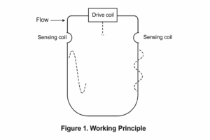
Coriolis meters operate by vibrating dual measuring tubes through an electromagnetic coil. The presence of fluid causes a Coriolis effect—twisting of the vibrating tubes—which is directly proportional to mass flow.

Figure 1: Working Principle Diagram

  • No flow: Tubes vibrate in phase

  • Flow present: Phase shift occurs between inlet and outlet ends

Signal Processing:

  • Drive coil maintains vibration

  • Two pickup coils detect phase shift

  • Mass flow calculated from the time difference between coils
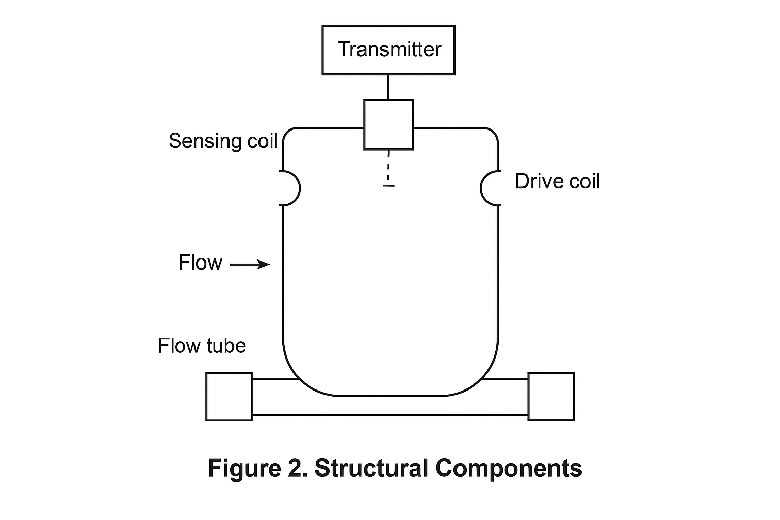
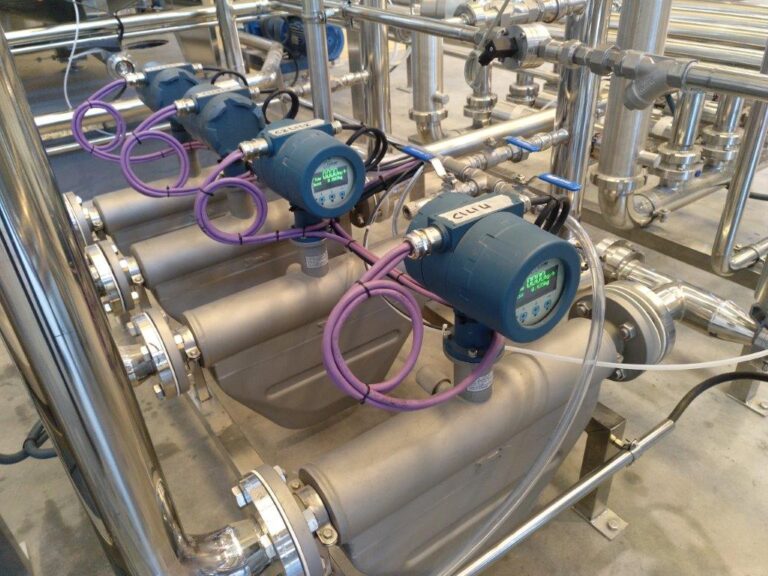
3. Meter Structure

Most Coriolis flow meters consist of:

  • Dual measuring tubes (U-shaped or straight)

  • Drive coil

  • Two pick-up coils (sensors)

  • Flow divider and flow manifolds

  • Transmitter housing (integrated or remote)

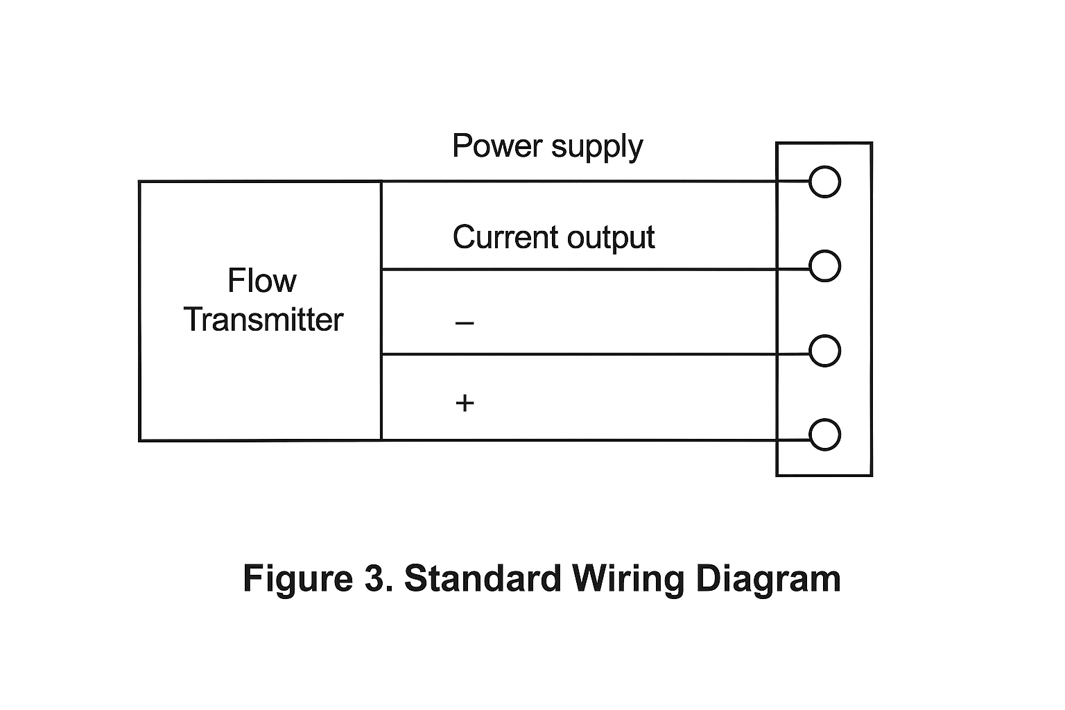
4. Electrical Wiring

Wiring varies by manufacturer, but standard industrial configurations include:

  • 4–20mA output: Terminals 1–2

  • Pulse/frequency output: Terminals 3–4

  • RS-485 digital output: Terminals 5–6

  • Power supply (24VDC or 220VAC): Terminals 9–10

Sensor Wiring Colors (Typical):

  • Drive coil: Brown (+), Red (–)

  • Sensor coil 1: Green (+), White (–)

  • Sensor coil 2: Blue (+), Grey (–)

  • PT100: Violet, Orange, Yellow (3-wire RTD)

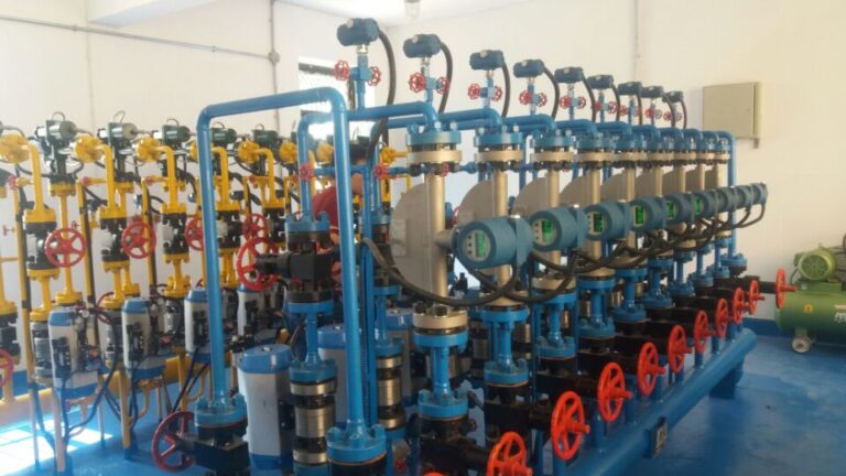
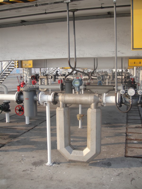
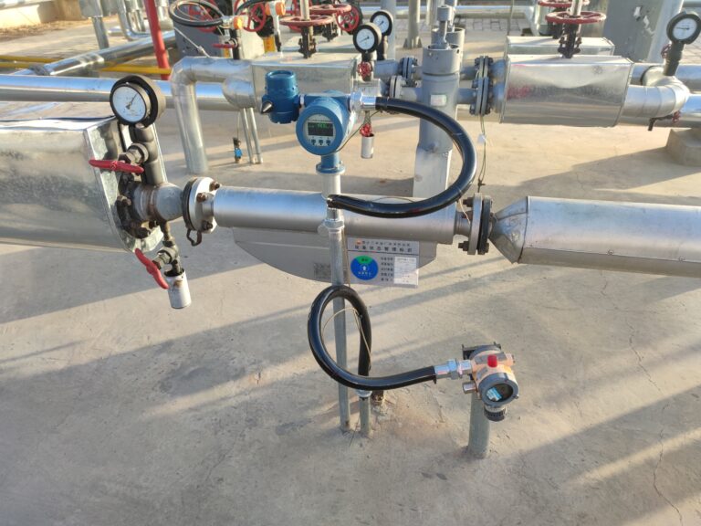
5. Installation Considerations

  • No straight pipe requirement, but sufficient space is needed for the meter body

  • Bidirectional measurement supported, but must match configuration direction

  • Support required near flanges to prevent stress from heavy body weight

  • Avoid vibration sources (e.g., pumps, compressors)

  • For vertical pipelines, liquid flow should be upward, gas flow can be upward or downward

  • Control valves should be installed downstream

  • For viscous or crystallizing media, ensure insulation or heating

6. Common Field Questions

QuestionAnswer
Is a straight pipe required?No, but support is essential.
Can it measure reverse flow?Yes, if properly configured.
Does vibration affect accuracy?Yes, avoid external vibrations.
24VDC vs 220VAC: Any performance difference?No, just power supply type.
Recommended zero-point check frequency?Every 3 months.
Should the meter be removed during pipeline purging?Yes, always.
Self-drain or cleaning for special fluids?Yes, must be considered.
Is heat tracing needed?Only if fluid requires it to prevent solidification.

7. Sensor Connector Pinout (9-Pin Plug Example)

PinFunction
1Drive Coil (+)
2Drive Coil (–)
3Sensor Coil 1 (+)
4Sensor Coil 1 (–)
5Sensor Coil 2 (+)
6Sensor Coil 2 (–)
7PT100 Wire A
8PT100 Wire B
9PT100 Wire C

8. Troubleshooting Cases

Case 1: Accuracy Lower than Expected

  • Symptoms: Field accuracy at ~0.3% vs expected 0.15%

  • Cause: Installed near vibration source; weak pipeline supports; unfilled pipe during operation

  • Solution: Increase distance from pump; strengthen supports; adjust valve for full pipe condition

Case 2: Cumulative Error After Pipeline Modification

  • Symptoms: Cumulative reading shows 8t; level gauge shows 5.7t

  • Cause: New pipe stress or partial flow due to air pockets or improper support

  • Solution: Reinforce support, ensure stress-free piping

Case 3: Sudden Jump in Flow Reading

  • Symptoms: Flow jumps from 2600 to 4200 Kg/h without process change

  • Cause: Possible transmitter program issue or electrical interference

  • Solution: Reboot or reprogram transmitter; inspect for EMI sources; check wiring

Case 4: Communication Fault A266

  • Symptoms: Zero data, alarm A266

  • Cause: Core processor disconnected or noise interference

  • Solution: Check wiring integrity, perform LED/power/resistance check, replace core if needed

9. Summary

Coriolis mass flow meters offer direct, accurate mass flow measurements across a wide range of applications. Proper installation, support, and environmental management are essential for reliable performance. Routine zero-point calibration and understanding fault codes can extend the service life and ensure operational consistency.

Share This Story, Choose Your Platform!

Contact Us

    Please prove you are human by selecting the cup.
    Translate »